


Parameter Descriptions 7-9
MN766
Block Title
Parameter (Number)
Selection (Value)
Parameter Name and Description
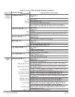
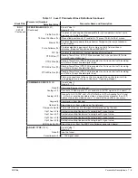
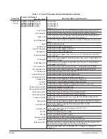
OUTPUT
SETUP
DIGITAL OUTPUT 1
(1501)
DIGITAL OUTPUT 2
(1502)
RELAY OUTPUT 1
(1503)
RELAY OUTPUT 2
(1504)
Preset Value: 1
Preset Value: 8
Preset Value: 9
Preset Value: 17
Range: 0 - 31
Drive Run (0)
Active when drive is “On” and a FWD/REV direction command is present.
Drive Ready (1)
Active after soft start, when drive is enabled and no faults are present.
Drive On (2)
(V/F) Active when drive is “Ready” and producing PWM to motor. (Vector)
Active when drive is “Ready” and motor fl ux is present.
Drive Stopped (3)
Active when stop command is present and motor is stopped (or coasting to
stop).
Jog (4)
Active during Jog mode.
Accelerate (5)
Active when control is accelerating.
Constant Speed (6)
Active when control speed is constant.
Decelerate (7)
Active when control is decelerating.
At Zero Speed (8)
Active when motor speed is less than the Level 1 Output Setup “Zero SPD
Set Pt (P1505)”.
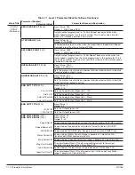
At Speed (9)
Active when motor speed is within band set by the Level 1 Output Setup “At
Speed Band (P1506)”.
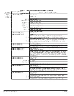
At Set Speed (10)
Active when output speed is at or greater than the Level 1 Output Setup
“Set Speed Point (P1507)”.
Curr Overload (11)
Active when motor current is greater than “Overload Set Point (P1508)”.
Curr Underload (12)
Active when motor current is less than “Underload Set Point (P1509)”.
I
2
T Overload (13)
Active when overload left is less than 100%.
Keypad Control (14)
Active when control is in Local keypad control.
Dynamic Brake (15)
Active when Dynamic Brake transistor is turned ON.
Foldback (16)
Active when current foldback is active (V/Hz Mode only).
Fault (17)
Active when a fault condition is present (will cause trip).
Alarm (18)
Active when an Alarm condition is present (but doesn’t cause trip).
Command Forward (19)
Active during forward run command.
Command Reverse (20)
Active during reverse run command.
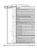
Motor Forward (21)
Active when motor is moving in Drive forward direction.
Motor Reverse (22)
Active when motor is moving in Drive reverse direction.
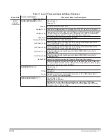
Process Error (23)
Active when absolute process error is greater than P2606 (Process Error
Tolerance).
Network (24)
Active when commanded by network. Network device controls this output.
At Position (25)
Active when load is at position (|Position error|≤P1517) AND
(|Motor Speed|≤P1505).
In Motion (26)
Active when load is moving (|Position error|>P1517) OR
(|Motor Speed|>P1505).
PLC (27)
Output is controlled by PLC mode.
RTC (28)
Output is controlled by RTC module.
Powered Up (29)
Active when Bus is “UP” and no faults are present.
Heater (30)
Output turns on when trickel current heating is active
Contactor Ctl (31)
Provides control of a contactor between the Control and the motor so that
the contactor is sequenced with the required time delays.
See also 1505, 1506, 1507, 1508,1509, 1517, Chapter 10, Chapter 11,
Chapter 12.
Table 7-1 Level 1 Parameter Block Defi nitions Continued
Содержание VS1SD
Страница 1: ...05 13 Installation Operating Manual MN766 VS1SD AC Servo Control...
Страница 12: ...2 2 General Information MN766...
Страница 16: ...3 4 Installing the Drive MN766...
Страница 108: ...7 34 Parameter Descriptions MN766...
Страница 114: ...8 6 Customizing Your Application MN766...
Страница 128: ...9 14 Troubleshooting MN766...
Страница 154: ...12 12 Monitor and RTC Description MN766...
Страница 188: ...E 2 Remote Keypad Mounting Template MN766...


