background image

  Using the Keypad   6-5

MN766

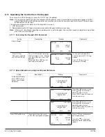
6.4  Basic Params

From the Menu display screen, select Basic Params and press Enter. 

Parameter Status

All programmable parameters are displayed with an “F” at the bottom center of the display. “F” means it is the factory 
setting value. “C” means it is a custom value set by the user. “V” means the parameter value may be viewed but not 
changed while the motor is operating. If the parameter is displayed with an “L”, the value is locked and may not be changed 
until the security code is entered.

Action

Description

Display

Comments

 Basic Params Display

Control type display.  The
parameter number “1601” is given
at the bottom center of the
display.“F”1601 indicates it is at
the factory setting and has not
been changed.

BASIC

STATUS

F1601T1

BACK

CONTROL TYPE

AC Servo

MOTOR CONTROL

 No other control selections are
 available.

Press 

 to go to the

next Basic Params
screen.

BASIC

F2413T1

BACK

MOTOR POLE PAIRS

2

MOTOR DATA

Press 

 to go to the

next Basic Params
screen.

BASIC

F2403T1

BACK

MOTOR RATED SPD

2500 RPM

MOTOR DATA

Press 

 to go to the

next Basic Params
screen.

BASIC

F2409T1

BACK

FEEDBACK SOURCE

Daughter FDBK

Press   to go to the
next Basic Params
screen.

BASIC

F2408T1

BACK

ENCODER COUNTS

1024 PPR

MOTOR DATA

MOTOR DATA 

Press 

 to go to the

next Basic Params
screen.

BASIC

F2402T1

BACK

MOTOR RATED AMPS

4.2 A

MOTOR DATA

STATUS

STATUS

STATUS

STATUS

STATUS

Содержание VS1SD

Страница 1: ...05 13 Installation Operating Manual MN766 VS1SD AC Servo Control...

Страница 2: ...re the property of their respective owners Important Be sure to check www baldor com for the latest software firmware and drivers for your VS1SD product Also you can download the latest version of thi...

Страница 3: ...es AA and B 3 3 Chapter 4 Power Wiring 4 1 Grounding the Drive 4 1 4 1 1 Ungrounded Distribution System 4 1 4 1 2 Input Power Conditioning 4 1 4 2 Line Impedance 4 2 4 2 1 Line Reactors 4 2 4 2 2 Load...

Страница 4: ...5 Preset Speeds 5 8 5 5 5 Fan Pump 2 Wire 5 9 5 5 6 Fan Pump 3 Wire 5 10 5 5 7 Process Control 5 11 5 5 8 3 Speed Analog 2 Wire 5 12 5 5 9 3 Speed Analog 3 Wire 5 13 5 5 10 E POT 2 Wire 5 14 5 5 11 E...

Страница 5: ...6 16 Chapter 7 Parameter Descriptions 7 1 Level 1 Parameters Advanced Prog Level 1 Blocks 7 1 7 2 Level 2 Parameters Advanced Prog Level 2 Blocks 7 15 7 3 Level 3 Parameters Advanced Prog Level 3 Bloc...

Страница 6: ...ix B Parameter Tables B 1 Level 1 Parameters Advanced Prog Level 1 Blocks B 1 B 2 Level 2 Parameters Advanced Prog Level 2 Blocks B 8 B 3 Level 3 Parameters Advanced Prog Level 3 Blocks B 12 Appendix...

Страница 7: ...WARNING Be sure that you are completely familiar with the safe operation of this equipment This equipment may be connected to other machines that have rotating parts or parts that are controlled by t...

Страница 8: ...hat requires no external power to operate CAUTION If a customer installed Dynamic Brake DB hardware mounting is in any position other than vertical the DB hardware must be derated by 35 of its rated c...

Страница 9: ...transient suppression is not adequate CAUTION Make sure that unexpected operation of the motor shaft during start up will not cause injury to personnel or damage to equipment Procedure Initial Condit...

Страница 10: ...Input 4 13 Digital Input 5 14 Digital Input 6 15 Digital Input 7 16 Digital Input 8 17 Digital Out 1 Collector 18 Digital Out 1 Emitter 19 Digital Out 2 Collector 20 Digital Out 2 Emitter For keypad...

Страница 11: ...r implied BALDOR shall not be held responsible for any expense including installation and removal inconvenience or consequential damage including injury to any person or property caused by items of ou...

Страница 12: ...2 2 General Information MN766...

Страница 13: ...s when run in close proximity to the drive Read the recommendations in the following sections before continuing with the drive installation 3 2 1 Location Instructions Before deciding on an installati...

Страница 14: ...er Cable Entrance I O Module Slot 1 Analog Digital I O Terminals I O Module Slot 2 Control Shield Plate Power Base Shield Screws 4 Power Motor Connections Cable Clamp and Shield Termination 3 5 Cover...

Страница 15: ...over on drive Ensure that gasket is seated in cover groove around the complete perimeter of the cover without any folds 3 While holding the cover against the base insert start and tighten all cover sc...

Страница 16: ...3 4 Installing the Drive MN766...

Страница 17: ...representative of actual terminal block arrangement Note 4 1 1 Ungrounded Distribution System With an ungrounded power distribution system it is possible to have a continuous current path to ground th...

Страница 18: ...unctions that include Protect the drive from a short circuit at the motor Limit the rate of rise of motor surge currents Slowing the rate of change of power the drive delivers to the motor Note The wi...

Страница 19: ...D 250A maximum all ratings Buss is a trademark of Cooper Industries Inc 4 5 Reduced Input Voltage Considerations Power ratings are for nominal AC input voltages 240 or 480VAC The power rating of the...

Страница 20: ...CUL AWG mm2 2A3 1 3 2 9 9 6 14 2 5 2A4 2 4 2 12 12 9 14 2 5 2A7 3 6 8 15 15 12 14 2 5 2A10 5 9 6 25 25 20 14 2 5 2A15 7 5 15 2 35 35 30 12 4 2A22 10 22 40 40 35 10 6 2A28 15 28 70 70 60 8 10 2A42 20...

Страница 21: ...A14 10 14 25 25 17 5 12 4 4A21 15 21 35 35 30 10 6 4A27 20 27 40 40 35 8 10 4A34 25 34 50 50 A70QS70 4 8 10 4A40 30 40 60 60 A70QS80 4 8 10 4A52 40 52 80 80 A70QS100 4 6 16 4A65 50 65 100 100 80 4 25...

Страница 22: ...TH1 Motor Thermal Leads Frame Size D Drives Dynamic Brake B R2 B R1 Motor Leads T3 T2 T1 Input AC Power Note An open circuit between TH1 and TH2 will cause an overtemperature fault Refer to fault tro...

Страница 23: ...7 7 3 4 2 15 15 12 14 2 5 14 2 5 2A10 11 8 6 8 20 20 15 14 2 5 14 2 5 2A15 16 6 9 6 25 25 20 10 6 14 2 5 2A22 19 11 30 30 25 10 6 14 2 5 2A28 24 14 40 40 35 10 6 12 4 2A42 36 21 60 60 50 8 10 10 6 2A5...

Страница 24: ...2110 should be set to Single Phase See recommended tightening torques in Table A 2 Figure 4 6 Size B and C Single Phase Power Connections to a 3 Phase Control L1 L2 L1 L2 L3 Earth Optional components...

Страница 25: ...wer and Motor Terminals see Cover Removal procedure 2 Feed the power supply and motor cables into the drive through the cable entrance 3 Connect the line L1 L2 N and GND to the power terminal connecti...

Страница 26: ...uld be 600 volts Figure 4 9 Typical Connections to Motor Control G N D TH1 TH2 Motor GND Motor Leads Motor Thermal Leads AC Servo Motor G U V W Motor Temperature Switch Shielded Twisted Pair Wire Moto...

Страница 27: ...er 4 Slide the Threaded Adapter onto the Contact Carrier until the Carrier is completely inserted into the Adapter 5 Slide the Gasket into the Contact Carrier 6 Slide the Adapter Cover onto the Thread...

Страница 28: ...es includes feedback device one threaded connector metric style for feedback termination of motor lead wires on terminal block IEC square mounting flange 3 Standard BSM motors do not have shaft seal M...

Страница 29: ...om the manufacturer to determine the pin out and or wire color codes Figure 4 14 Typical Connections to Feedback Termination Resolver Function R1 REF HI R2 REF LO S1 COS S3 COS S2 SINE S4 SINE Open 8...

Страница 30: ...he following procedure 1 Remove all power from the control Wait 5 minutes for bus capacitors to discharge Open cover 2 Place resolver expansion board jumper J3 in the desired position see Figure 4 13...

Страница 31: ...al Input 4 13 Digital Input 5 14 Digital Input 6 15 Digital Input 7 16 Digital Input 8 17 Digital Out 1 Collector 18 Digital Out 1 Emitter 19 Digital Out 2 Collector 20 Digital Out 2 Emitter Terminals...

Страница 32: ...Input 7 J2 16 DIN8 Digital Input 8 J2 17 Digital Output 1 Collector J2 18 Digital Output 1 Emitter J2 19 Digital Output 2 Collector J2 20 Digital Output 2 Emitter Table 5 3 J3 Connector De nition Conn...

Страница 33: ...egative with respect to pin J1 5 and P1408 5V or 10V the motor will rotate in the reverse direction If forward direction is not correct change Level 2 Motor Data Reverse Rotation parameter P2415 Analo...

Страница 34: ...LOW Sinking Relationship Enable J2 Digital Input 2 Digital Input 3 Digital Input 4 Digital Input 5 Digital Input 6 Digital Input 7 Digital Input 8 21 J3 22 23 24 Active High Connections User Provided...

Страница 35: ...required However the Stop and External Trip inputs may optionally be used All other Digital Inputs remain inactive The Analog Outputs and Digital Outputs remain active at all times Figure 5 5 Keypad C...

Страница 36: ...motor coasts to a stop J2 9 CLOSED starts motor operation in the Forward direction OPEN motor decels to stop If Level 1 Keypad Setup Stop Mode is set to coast motor coasts to stop J2 10 CLOSED starts...

Страница 37: ...before connecting switch at J2 8 J2 8 CLOSED allows normal operation OPEN disables the control and motor coasts to a stop J2 9 MOMENTARY CLOSED starts motor operation in the Forward direction In JOG m...

Страница 38: ...elects programmed Preset Speeds as defined in Table 5 4 J2 15 CLOSED selects ACC DEC S ACC S DEC group 2 OPEN selects ACC DEC S ACC S DEC group 1 J2 16 Optional External Trip input not required If use...

Страница 39: ...pen OPEN motor decels to stop Note J2 9 and J2 10 are both closed Fault Reset J2 11 CLOSED selects Analog Input 1 if J2 13 J2 14 and J2 15 are closed OPEN selects Command Source Level 1 Input Command...

Страница 40: ...the Forward direction Note Closing both J2 9 and J2 10 at the same time will reset a fault J2 10 MOMENTARY CLOSED starts motor operation in the Reverse direction Note Closing both J2 9 and J2 10 at t...

Страница 41: ...Forward speed command is still present Reverse operation is still possible if J2 10 is closed J2 10 CLOSED to enable operation in the Reverse direction OPEN to disable Reverse operation drive will dec...

Страница 42: ...the motor in the Reverse direction with J2 9 open OPEN motor decels to stop Note Closing both J2 9 and J2 10 at the same time will reset a fault J2 11 CLOSED selects Analog Input 1 OPEN selects Level...

Страница 43: ...CLOSED allows normal control operation OPEN disables the control and the motor coasts to a stop J2 9 MOMENTARY CLOSED starts motor operation in the Forward direction J2 10 MOMENTARY CLOSED starts mot...

Страница 44: ...ve factory jumper from J2 8 and J3 24 before connecting switch at J2 8 J2 8 CLOSED allows normal control operation OPEN disables the control and the motor coasts to a stop J2 9 CLOSED starts motor ope...

Страница 45: ...20 See recommended tightening torques in Table A 2 Note Remove factory jumper from J2 8 and J3 24 before connecting switch at J2 8 J2 8 CLOSED allows normal control operation OPEN disables the control...

Страница 46: ...ation drive will decel to a stop if a Network Forward command is still present Reverse operation is still possible if J2 10 is closed J2 10 CLOSED to enable operation in the Reverse direction OPEN to...

Страница 47: ...SED to enable operation in the Forward direction OPEN to disable Forward operation drive will decel to a stop if a Forward profile run command is still present Reverse operation is still possible if J...

Страница 48: ...PEN to disable Reverse operation drive will decel to a stop if a Reverse reference command is still present Forward operation is still possible if J2 9 is closed Note If J2 9 and J2 10 are both opened...

Страница 49: ...e until you have first selected that table Note The active parameter table is selected by Level 2 Drive Configure Active Parameter Table P0052 Example Before attempting to switch parameter tables duri...

Страница 50: ...utput 2 See Figure 5 4 for connection information Note Remove factory jumper from J2 8 and J3 24 before connecting switch at J2 8 One input must be a direction input FWD or REV 5 6 Digital Outputs Dig...

Страница 51: ...il install an RC Snubber across the coil to reduce noise transmission RC Snubber 0 47 f 33 See recommended tightening torques in Table A 2 Control Board Note Relay Outputs are rated to 10 30VDC or 240...

Страница 52: ...24 The baud rate and node addresses are selectable from the Keypad Jumper JP3 Figure 5 24 on the control board sets termination As shown pins 2 and 3 jumpered no terminating resistor is used Setting...

Страница 53: ...nable Digital Input 1 Digital Input 2 Digital Input 3 Digital Input 4 Digital Input 5 Digital Input 6 See Figure 5 4 for connection information Opto In Common 5 11 Opto Isolated Outputs The outputs ar...

Страница 54: ...Watts parameters 7 Enable the control J2 8 connect to J3 24 WARNING The motor shaft will rotate during this procedure Be certain that unexpected motor shaft movement will not cause injury to personnel...

Страница 55: ...required by Windows 1 The software must be downloaded from the Baldor site http www baldor com Simply log into that web site and select Products then select AC Controls then select VS1 Series AC Servo...

Страница 56: ...27 and locate 1 Mint WorkBench v X x 3 Click on Download the software and run the installation program 4 When installation is complete the Mint WorkBench program will start see Figure 5 28 a Click Sta...

Страница 57: ...ile is saved in My Documents My Mint directory 7 When complete the entire project can be saved to your PCs hard disk for future use Click File Save File see Figure 5 31 The WBX file is saved in C Prog...

Страница 58: ...int Machine Center Firmware VS1 Servo SHH_1_20 chx This procedure erases memory and restores factory settings All user data will be lost After the firmware download all user data values must be reprog...

Страница 59: ...key Up Arrow Down Arrow Left Arrow Right Arrow Moves cursor to select menu choices ENTER Press ENTER to save parameter value changes In the display mode the ENTER key is used to directly set the loca...

Страница 60: ...S FWD LOCAL DIAG 600r MAIN 159 5V 600RPM 6 2A 20 0HZ Prog Mode Display Features The first character of the parameter number PROG STATUS BACK PRESET SPEED 1 30RPM F1001T1 PRESET SPEEDS Parameter Table...

Страница 61: ...LT 230 0V Press key Next screen format is displayed 0 0A STOP LOCAL DIAG 0 00r MAIN Press key Next screen format is displayed STOP LOCAL DIAG 0 00r MAIN Press key Next screen format is displayed STOP...

Страница 62: ...0HZ STATUS Action Description Display Comments 6 3 Menu Display After power up the display shows the Status screen Press the Menu key to display menu options Action Description Display Comments Status...

Страница 63: ...play The parameter number 1601 is given at the bottom center of the display F 1601 indicates it is at the factory setting and has not been changed BASIC STATUS F1601T1 BACK CONTROL TYPE AC Servo MOTOR...

Страница 64: ...the next Basic Params screen BASIC Press to go to the next Basic Params screen BASIC BACK END OF BASIC PARAMS F2003T1 BACK MAX OUTPUT SPEED 2500 RPM DRIVE LIMITS DRIVE LIMITS RAMP RATES F2202 T1 BACK...

Страница 65: ...parameter value the function of the F1 key previous parameter block shown in the lower left of the display changes to one of the following to help select the parameter value TOP Press F1 to display a...

Страница 66: ...eral controls operate the same It prevents having to make the changes to each control individually Action Description Display Comments Press Menu Go to the Advanced Prog Level 1 Keypad Setup block PRE...

Страница 67: ...having to make the changes to each control individually Action Description Display Comments Press Menu Go to the Level 1 Keypad Setup block PRESET SPEEDS RAMP RATES JOG SETTINGS KEYPAD SETUP INPUT SE...

Страница 68: ...Level 3 blocks Press to view list of parameters that have been changed from their factory settings or to view a list of parameters organized by number Press Enter to edit Level 1 parameters Top of Lev...

Страница 69: ...o to next modified parameter Press F2 to return to Advanced Prog menu parameter 6 7 2 Linear List Action Description Display Comments Advanced Prog Display Top Level Advanced Prog menu LEVEL 1 BLOCKS...

Страница 70: ...4 F1005 PRESET SPEED 5 Use cursor keys to position cursor and increase or decrease each character under the cursor as desired Press Enter when finished Press F2 to return to previous menu The newly s...

Страница 71: ...nd Amp Volt ratings STATUS 0 00r MAIN SHH 1 21 RATED HP 3HP RATED VOLTS 240 0V RATED A V 4 0A V DIAG STOP LOCAL Press to go to the next or previous Diagnostic screen Press F2 to return to main menu Pr...

Страница 72: ...ess F1 to go to Status screen Press to display next group Displays Composite Reference values STATUS 0 00r COMPOSITE REF COMPONENT A 0 00 COMPONENT B 0 00 REFERENCE 0 00 DIAG STOP LOCAL Press to displ...

Страница 73: ...YPAD CONTRAST 50 Press Enter to change parameter value Press to display next screen Press F2 to return to previous menu or PROG KEYPAD SETUP DIAG F1314T1 BACK BACKLIGHT On Press Enter to change parame...

Страница 74: ...ating the JOG mode is active Holding the FWD or REV key starts JOG operation Releasing FWD or REV key will terminate motor rotation STATUS FWD LOCAL DIAG 210r MAIN 10 1V 210RPM 1 3A 7 0HZ To change Jo...

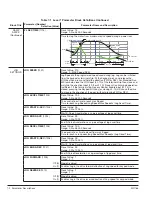
Страница 75: ...o terminals at J2 For motor operation a motor direction command must be given along with a preset speed command RAMP RATES ACCEL TIME 1 1101 ACCEL TIME 2 1107 Preset Value 3 0 Range 0 0 to 3600 0 Seco...

Страница 76: ...will cause the drive to move in the direction of the error without pressing FWD or REV JOG ACCEL TIME 1202 Preset Value 10 0 Range 0 0 to 3600 0 Seconds The accel rate or time to reach max Speed Time...

Страница 77: ...ocal mode On 1 Makes the keypad REV key active in Local mode SWITCH ON FLY 1305 LOCAL REMOTE KEY Preset Value 0 Range 0 1 Off 0 Disables Switch on Fly On 1 Allows switching between Local and Remote wh...

Страница 78: ...only Standard Run 2Wire 1 Drive operates from digital inputs and command source Preset Speed 1 may also be selected Standard Run 3Wire 2 Drive operates from digital inputs and command source Preset S...

Страница 79: ...D 2 Wire provides for 3 wire control with reversing and Trickle Current Enable digital input External connections to the control are made at the control terminal strip wiring diagrams are shown in Cha...

Страница 80: ...pplied as in Y Gain X Offset ANA IN1 OFFSET 1406 ANA IN2 OFFSET 1411 Preset Value 0 0 Range 100 0 to 100 0 Provides an offset to the Analog Input to minimize signal error For example if the minimum sp...

Страница 81: ...igh resolution analog input output Expansion Board EXBHH005 mounted in expansion slot 1 Opt2 Ana In1 7 Selects analog input output Expansion Board EXBHH005 mounted in expansion slot 2 Opt2 Ana In2 8 S...

Страница 82: ...Chapter 11 for more information Opt1 Ana In1 5 Selects analog input from high resolution analog input output expansion Board EXBHH005 mounted in expansion slot 1 Opt1 Ana In2 6 Selects analog input f...

Страница 83: ...rload Set Point P1509 I2 T Overload 13 Active when overload left is less than 100 Keypad Control 14 Active when control is in Local keypad control Dynamic Brake 15 Active when Dynamic Brake transistor...

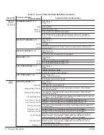
Страница 84: ...which the Underload digital output is active ANA OUT1 TYPE 1510 Preset Value 0 Range 0 3 0 to 10V 0 Sets the Analog Output Signal to 0 10V 0 to 5V 1 Sets the Analog Output Signal to 0 5V 4mA to 20mA 2...

Страница 85: ...P1408 Opt1 Ana In1 21 Scaled value of option board 1 analog input 1 signal value range depends on input type selected Opt1 Ana In2 22 Scaled value of option board 1 analog input 2 signal value range...

Страница 86: ...ts the feedback s electrical direction in reverse rotation Sets the feedback s electrical direction of rotation to match that of the motor FEEDBACK FILTER 1632 Preset Value 4 Range 0 7 A larger value...

Страница 87: ...HEAT AMPS 1678 Preset Value 0 0 Range 0 0 50 0 of Motor Rated Amps Used to provide heating amps in the motor windings while the motor is stopped to help eliminate condensation within the motor A value...

Страница 88: ...Range 0 1 No 0 No Action Yes 1 Reset settings Restores factory settings to Browser User ID and Password BROWSER USER ID 1707 1708 Preset Value baldor ASCII user ID for the Ethernet Web Browser Option...

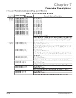
Страница 89: ...tor starts or during dynamic braking to a stop MAX OUTPUT SPEED 2003 Preset Value 2500 Range 30 0 15 000 RPM Sets the maximum motor speed in RPM PWM FREQUENCY 2004 Preset Value 8000 Range 5000 16000Hz...

Страница 90: ...otal 3 Security enabled for both Keypad and Network Enables Security ACCESS TIMEOUT 2106 Preset Value 5 0 Range 1 0 600 0 seconds If security is enabled and program mode is entered the access code mus...

Страница 91: ...e value from 2 to 0 to avoid Loss of Phase trips EXECUTE MACRO 2112 Preset Value 0 Range 0 5 No 0 Do not execute macro M1 1 Execute Macro M1 M2 2 Execute Macro M2 M3 3 Execute Macro M3 M4 4 Execute Ma...

Страница 92: ...Hold 2 Drive attempts to reduce current to 100 of drive rated current so that time remaining can hold at present value Sets how the control handles I2 T power overloads When an overload occurs it wil...

Страница 93: ...a non zero value Auto restarts disabled at power up but enabled after a fault Both 3 Auto restarts active at power up and after faults 3 Wire modes AUTO start after a fault or loss of power will not...

Страница 94: ...Sets the auxiliary filter to None Low Pass 1 Sets the auxiliary filter to Low Pass High Pass 2 Sets the auxiliary filter to High Pass Notch 3 Sets the auxiliary filter to Notch FILTER SOURCE 2310 Pre...

Страница 95: ...r feedback counts in lines per revolution FEEDBACK SOURCE 2409 Preset Value LEAVE AT DEFAULT SETTING Range 0 3 None 0 No encoder option board Option Slot1 1 Feedback option board location is Option Sl...

Страница 96: ...additional information RESISTOR WATTS 2502 Preset Value CALC Range 0 999999W The dynamic braking resistor watts rating RESISTOR TTC 2503 Preset Value CALC Range 20 3600 seconds Sets the time for heat...

Страница 97: ...ork value used for Setpoint Composite Ref 6 Output of Composite Ref signal used for Setpoint Opt1 Ana In1 7 Option 1 Analog Input 1 used for Setpoint Opt1 Ana In2 8 Option 1 Analog Input 2 used for Se...

Страница 98: ...is active control is disabled motor coasts If at any time the process error moves out of this band sleep mode is terminated and normal PID operation is resumed Zero Disables sleep mode PROC OUT FILTE...

Страница 99: ...tionery test will not cause motor shaft rotation CUR LOOP TUNE 2906 Preset Value 0 Range 0 1 No 0 No action Yes 1 Tunes the current controller loop FLUX CUR TUNE 2907 Preset Value 0 Range 0 1 No 0 No...

Страница 100: ...ILE TIME 3 3008 PROFILE TIME 4 3010 PROFILE TIME 5 3012 PROFILE TIME 6 3014 PROFILE TIME 7 3016 Preset Value 0 00 Range 0 99999 00 seconds Sets the amount of time Profile Run stays at a preset speed T...

Страница 101: ...ue INCREMENT STEP 3105 Preset Value 1 Range 1 1024 Output portion of the selected I O ratio or absolute position is changed by this RX RATIO INPUT 3106 Preset Value 1024 Range 1 1048576 Receive Input...

Страница 102: ...aling Normal status display used until y is set to a non zero value The value X X is displayed at Y RPM Note that Y RPM is programmed in parameter P3204 AT SPEED VALUE when using Mint WorkBench UNITS...

Страница 103: ...tive if the Master Pulse Reference Isolated Pulse Follower EXB EXBHH007 is installed Only displayed when Level 1 Input Setup Operating Mode parameter P1401 is set to Preset Position POS INTG CLAMP 333...

Страница 104: ...tor real time signals within the drive and apply them to the PLC Mode s logic The setting of these parameters is the number of the parameter to be monitored by the comparator They may be used on the c...

Страница 105: ...nd second parameters See Chapter 11 FUNCTION 3506 Preset Value 1 Range 0 9 Zero 0 Identity 1 Absolute Value 2 Invert 3 Square 4 Square Root 5 Sine 6 Cosine 7 Ramp Generator 8 Freq Generator 9 Mathemat...

Страница 106: ...1 On IncP107 18 R Out1 Off IncP107 19 R Out1 On DecP107 20 R Out1 Off DecP107 21 R Out1 On Reset 22 R Out1 Off Reset 23 First action taken as a result of an edge from the RTC See Chapter 12 Second act...

Страница 107: ...12 ACT1 DATE TIME 3609 ACT2 DATE TIME 3610 Preset Value 01 January 2000 00 00 00 Range 01 January 2000 00 00 00 31 December 2063 23 59 59 Schedule qualifier for the RTC message 1 See Chapter 12 Sched...

Страница 108: ...7 34 Parameter Descriptions MN766...

Страница 109: ...the error The summing junction compares the measured value of the controlled variable Feedback Input with the Input Command desired value and generates an error signal The operation is a simple mathe...

Страница 110: ...we see that the amplitude of the output of the control is dependent on the error multiplied by the proportional gain For a given amount of error the greater the proportional gain the greater the outp...

Страница 111: ...and corrects the control output to reduce the effect of offset Integral Gain is mathematically defined as Aout Ki t Where Aout Controller output Ki Integral gain Integrator symbol Process error signal...

Страница 112: ...appens when the proportional gain is increased from 25 to 100 An increase in the proportional gain causes the controlled variable to respond more quickly as indicated by the feedback signal Feedback I...

Страница 113: ...op Gain parameter will result in faster response excessive proportional gain will cause overshoot and ringing Decreasing the Speed Prop Gain parameter will cause slower response and decrease overshoot...

Страница 114: ...8 6 Customizing Your Application MN766...

Страница 115: ...G EVENT LOG DIAGNOSTICS DIAG BACK Press to move cursor over the EVENT LOG selection Press Enter to view the event log Event Log Display LOW INITIAL BUS 0 Date Time Entry 0 9 HH MM SS Displays error na...

Страница 116: ...e fault on Motor Phase 3 8000 1000 0000 0000 0000 Inverter Desaturation Fault Trace Displays Continued Action Description Display Comments Fault Trace Display The Alarm Latch word is also displayed Th...

Страница 117: ...ER INPUTS 100000000 EV LOG Press to view next entry This is a bit display not a hex value or or or Fault Trace Display Next is the status of the Digital Output signals The below table indicates the fu...

Страница 118: ...BACK PH1 CURRENT 0 0 A EV LOG FAULT TRACE Press to view next entry or or or or Next is the AC output current on phase 2 STATUS T0003 BACK PH2 CURRENT 0 0 A EV LOG FAULT TRACE Press to view next entry...

Страница 119: ...F2 to return to the event log or or or Next is the Motor Voltage STATUS T0003 BACK MOTOR VOLTS 0 0V EV LOG FAULT TRACE Press to view next entry Next is the Motor Speed T0003 BACK MOTOR SPEED 0 RPM EV...

Страница 120: ...A V 4 0A V DIAG STOP LOCAL Press to go to the next or previous Diagnostic screen Press F2 to return to main menu or Note Example display shows that the drive enable terminal J2 8 is on and that Relay...

Страница 121: ...n display POSITION COUNTER REVOLUTION COUNTS 0 0CNT Full revolutions and feedback counts are displayed OPTION BOARDS OPTION 1 ETHERNET OPTION 2 MASTER PF FEEDBACK RESOLVER Press F1 to go to Status scr...

Страница 122: ...ROM contact Baldor for service Control EE Fault 32 Problem writing a parameter to the control board EEPROM contact Baldor for service Conv Over Temp Alarm 98 Converter has overheated decrease loading...

Страница 123: ...ed slot Select an Encoder Resolver board as feedback source Verify selection of correct slot for motor feedback Invalid Res Sel Alarm 71 The feedback source selected is not a resolver board If resolve...

Страница 124: ...ption Board for the feature requested is not installed Verify slot location for expansion board to support desired feature install appropriate option board for requested feature Over Current Fault 6 M...

Страница 125: ...ability Regen R or PWR Fault 25 Brake resistor power rating exceeded Check resistor ratings extend decel times increase size of braking kit Resolver Loss Fault 72 Resolver signal poor or missing Verif...

Страница 126: ...and motor Verify motor windings are not shorted Upper W Gate Fault 43 Transistor 3 failed to fire or misfired Verify IGBT is not shorted Verify no debris has fallen into drive Check wiring between dr...

Страница 127: ...place line conductors and load conductors in same conduit Use one conduit for 3 phase input wires and another conduit for the motor leads The conduits should be grounded to form a shield to contain t...

Страница 128: ...9 14 Troubleshooting MN766...

Страница 129: ...er Number Format DDD CCC BBB AAA Example P3401 051 000 000 020 A configuration parameter may be disabled turned off by setting bit 23 in its configuration word This is the same as setting the most sig...

Страница 130: ...A B then True else False For example if P3431 103 Analog Input 1 Reference with Max 100 and P3433 104 Analog Input 2 Reference with Max 100 then Condition 88 would be true so long as P103 P104 or so l...

Страница 131: ...drive hardware enable is on and there are no errors this condition is True 24 Drive On If the drive is ready and producing PWM to the motor this condition is True 25 Fault If the drive is faulted for...

Страница 132: ...eters 78 Parameter Table 1 If parameter table 1 is active then this condition is True 79 Parameter Table 2 If parameter table 2 is active then this condition is True 80 Parameter Table 3 If parameter...

Страница 133: ...Workbench Error Deceleration 10 Reserved Workbench Cancel 11 Reserved Workbench Disable 12 Reserved Workbench Forced Abort 13 Reserved Workbench Fast Gear 18 Jog Enable Allows jogging if True else jog...

Страница 134: ...e input condition is True then the drive controls torque else it controls speed Default is speed control NOTE For V F torque control is not supported and is ignored 39 Seed E Pot If the condition is t...

Страница 135: ...C Actions Description 28 27 26 25 0 0 0 0 Preset Speed 1 P1001 Selected 0 0 0 1 Preset Speed 2 P1002 Selected 0 0 1 0 Preset Speed 3 P1003 Selected 0 0 1 1 Preset Speed 4 P1004 Selected 0 1 0 0 Preset...

Страница 136: ...Ref Power 1 2 3 4 5 6 7 J1 Analog Input 2 Analog Input 2 Analog Output 1 Analog Output 2 Enable J2 Digital Output 1 Collector Digital Output 1 Emitter Digital Output 2 Collector Digital Output 2 Emitt...

Страница 137: ...000 019 Input 8 57 NOR 3 False 0 Fault 19 User Analog Return Analog Input 1 Analog Ref Power 1 2 3 4 5 6 7 J1 Analog Input 2 Analog Input 2 Analog Output 1 Analog Output 2 Enable J2 Digital Output 1...

Страница 138: ...9 Input 8 57 NOR 3 False 0 Fault 19 User Analog Return Analog Input 1 Analog Ref Power 1 2 3 4 5 6 7 J1 Analog Input 2 Analog Input 2 Analog Output 1 Analog Output 2 Enable J2 Digital Output 1 Collect...

Страница 139: ...23 Input 7 56 OR 0 False 0 Reset 23 P3410 057 000 000 050 Input 8 57 OR 0 False 0 Start Timer 50 P3411 086 000 000 019 Timer A 86 OR 0 False 0 Fault 19 User Analog Return Analog Input 1 Analog Ref Pow...

Страница 140: ...ve 12 Hz if input 4 is ON The PID becomes active at less than 12 Hz when input 4 is OFF The Fault action is programmed to trigger after a three second delay following digital input 8 going low Timer A...

Страница 141: ...enerator Block Diagram Stage 1 P 3501 3507 Scale Factor Py Px Max Px Py Px Variable A Stage 1 P 3503 3508 Scale Factor Pb Pa Max Pa Pb Variable B P a Output is 100 Output is 100 Stage 2 P 3502 Math Fu...

Страница 142: ...Table 11 1 3 3505 Operator This parameter provides the mathematical operation to be performed at the third stage of the Composite Reference derivation Refer to Table 11 2 1 3507 3508 These parameters...

Страница 143: ...e speed output from Speed Profiler 11 SPEED DEMAND Hz Speed Demand Signed speed output from Speed Profiler 12 ABS MOTOR FREQ Hz Absolute Motor Frequency Estimated motor electrical frequency 13 MOTOR F...

Страница 144: ...ured value of analog input 2 on terminal input J1 4 and J1 5 41 ANA OUT1 V Analog Output 1 Estimated value of analog output 1 on terminal J1 6 42 ANA OUT2 V Analog Output 2 Estimated value of analog o...

Страница 145: ...plication Layer Error Application layer error code number The last error that occurred 70 USB TRANSACTIONS USB Transactions Total number of USB transactions since start up 71 USB ERRORS USB Errors Tot...

Страница 146: ...on Following Error Difference Between Position Demand and Rotor Position 97 POS COUNTER CNT Position Counter In accordance with feedback device 98 LV TEST FEEDBACK LV test feedback Gives feedback on s...

Страница 147: ...ce power up Encoder PPR parameter sets the revolution count 503 OPT1 ANA IN1 V mA Option 1 Analog Input 1 Option board 1 analog input 1 504 OPT1 ANA IN2 V mA Option 1 Analog Input 2 Option board 1 ana...

Страница 148: ...Slot 2 option card s run time status 536 OPT1 ANA1 REF Option Card 1 Analog Input 1 Reference Reference generated from analog input 1 on option card 1 537 OPT1 ANA2 REF Option Card 1 Analog Input 2 Re...

Страница 149: ...mperature 12 2 Real Time Clock RTC Overview Action Module Action Module parameters P3601 3602 set the actions to be scheduled Action 2 takes priority over action 1 should both be scheduled to trigger...

Страница 150: ...17 Digital Output 1 Off with Reset Performs digital I O with P107 reset 18 Relay Output 1 On with Inc Performs digital I O with P107 increment 19 Relay Output 1 Off with Inc Performs digital IO with...

Страница 151: ...ear 00 63 Month 1 12 Day 1 31 Hour Bit 5 Hour Bits 4 0 0 23 Minutes 0 59 Seconds 0 59 RTC Counter and Maximum Count Parameters P107 and P3630 Monitor parameter P107 is a general purpose RTC Counter th...

Страница 152: ...on the tenth of every month after lunch starting January 10 2006 In addition once a year on the 10 of July the heating system is serviced after lunch as well RTC messages 1 2 are not logged but must...

Страница 153: ...and save the new value See RTC chapter of this manual for additional details Press to go to the next RTC screen Each RTC parameter can be changed by using the procedure described for RTC ACTION 1 EDIT...

Страница 154: ...12 12 Monitor and RTC Description MN766...

Страница 155: ...t for position loop controller simulated resolver 1024 ppr quadrature with index Protective Features Servo Trip Missing control power over current over voltage under voltage motor over speed resolver...

Страница 156: ...hing Automatic tuning to motor with manual override PC Setup Software Mint WorkBench software available using USB2 0 port for commissioning wizard firmware download parameter viewer scope capture and...

Страница 157: ...aximum ON Voltage Drop 2VDC Maximum OFF Leakage Current 0 1A Maximum Output Conditions 31 Conditions see Output Setup Block parameter table Chapter 7 Digital Outputs 2 Relay Outputs Rated Voltage 5 to...

Страница 158: ...0 23 5 0 56 VS1SD2A54 1B 35 4 35 4 35 4 4 0 45 2 0 23 5 0 56 VS1SD2A68 1B 35 4 35 4 35 4 4 0 45 2 0 23 5 0 56 VS1SD2A80 1B 35 4 35 4 35 4 4 0 45 2 0 23 5 0 56 VS1SD2A104 1B 180 20 3 80 9 1 50 5 6 6 0...

Страница 159: ...Return Authorization Number and any return shipments must be prepaid Figure A 1 Drive Identi cation VS1SD 4 A15 1 B Voltage Code 2 240VAC 3PH 4 480VAC 3PH 6 120 240VAC 1PH Current Rating VS1SD Servo C...

Страница 160: ...13 6 9 6 9 6 16 8 VS1SD2A10 1B 4B 240 AA 9 6 9 6 19 2 15 2 15 2 26 6 VS1SD2A15 1B 4B 240 AA 15 2 15 2 30 4 22 22 38 5 VS1SD2A22 1B 240 B 22 22 44 28 28 49 VS1SD2A28 1B 240 B 28 28 56 42 42 74 VS1SD2A...

Страница 161: ...8 12 VS1SD2A42 1B 18 6 18 6 18 6 24 14 30 14 28 12 VS1SD2A54 1B 8 1 8 1 8 1 24 14 30 14 28 12 VS1SD2A68 1B 8 1 8 1 8 1 24 14 30 14 28 12 VS1SD2A80 1B 8 1 8 1 8 1 24 14 30 14 28 12 VS1SD2A104 1B 14 3 0...

Страница 162: ...35 dia B1 0 35 8 9 B C Exhaust A A1 B1 0 35 8 9 CONDUIT INFORMATION 3 1 109 28 2 2 1 375 34 9 B N4X 3 1 115 28 3 Table A 5 Mounting Dimensions Size Dimensions inches mm Weight Outside Mounting Height...

Страница 163: ...300 PRESET SPEED 11 1011 0 MAX Speed 330 PRESET SPEED 12 1012 0 MAX Speed 360 PRESET SPEED 13 1013 0 MAX Speed 390 PRESET SPEED 14 1014 0 MAX Speed 420 PRESET SPEED 15 1015 0 MAX Speed 450 RAMP RATES...

Страница 164: ...1311 0 All 1 Motor 2 Other 0 KEYPAD TO PARAMS 1312 0 No 1 Yes 0 KEYPAD CONTRAST 1313 0 100 0 dimmest 100 brightest 50 BACKLIGHT 1314 0 Off 1 On 1 LOC TORQUE MODE 1315 0 Off 1 On 0 LOC TORQUE REF 1316...

Страница 165: ...ERT 1409 0 Off 1 On 0 ANA IN2 GAIN 1410 0 0 to 300 0 100 0 ANA IN2 OFFSET 1411 100 0 to 100 0 0 0 ANA IN2 D BAND 1412 0 0 to 75 0 0 0 ANA IN2 FILTER 1413 0 No Filter to 6 Max Filter 0 EXT CUR LIMIT 14...

Страница 166: ...ke 16 Foldback 17 Fault 18 Alarm 19 Command Forward 20 Command Reverse 21 Motor Forward 22 Motor Reverse 23 Process Error 24 Network 25 At Position 26 In Motion 27 PLC 28 RTC 29 Powered Up 1 DIGITAL O...

Страница 167: ...2 Current 11 Ph3 Current 12 Motor Voltage 13 VD Demand 14 VQ Demand 15 Bus Voltage 16 Abs Torque 17 Torque 18 Control Temp 19 Analog In1 20 Analog In2 21 Opt1 Ana In1 22 Opt1 Ana In2 23 Opt2 Ana In1 2...

Страница 168: ...33 Power kW 34 Calibrate 3 ANA OUT2 GAIN 1515 0 0 200 0 100 0 CAL ANA OUT 1516 100 0 to 100 0 0 0 AT POS BAND for Feedback Device Only 1517 1 to 4095 Counts 10 MOTOR CONTROL CONTROL TYPE 1601 3 AC Ser...

Страница 169: ...04 1 247 1 OPT CARD RESET 1705 0 Off 1 Slot 1 2 Slot 2 3 Slots 1 2 0 SECURITY DEFAULT 1706 0 No 1 Yes 0 BROWSER USER ID 1707 ASCII user ID for the Ethernet Web Browser Option Board if installed baldor...

Страница 170: ...E CONFIGURE SPEED UNITS 2101 0 Hz 1 RPM 1 LANGUAGE SELECT 2102 0 English 1 Other Spanish German Italian French or Portuguese 0 FACTORY SETTINGS 2103 0 No 1 Yes 0 SECURITY 2105 0 Off 1 Local 2 Network...

Страница 171: ...No 1 Yes 0 HOMING SPEED 2307 0 MAX Speed RPM 90 HOMING OFFSET 2308 9999 to 20000 counts 1024 FILTER TYPE 2309 0 None 1 Low Pass 2 High Pass 3 Notch 0 FILTER SOURCE 2310 0 None 1 Raw Speed 2 Torque 3 A...

Страница 172: ...ef 3 Analog In1 4 Analog In2 5 Network 6 Composite Ref 7 Opt1 Ana In1 8 Opt1 Ana In2 9 Opt2 Ana In1 10 Opt2 Ana In2 0 SETPOINT SOURCE 2604 0 None 1 Setpoint Cmd 2 Local Speed Ref 3 Analog In1 4 Analog...

Страница 173: ...tory User Setting AUTO TUNE ANA OFFSET TRIM 2901 0 No 1 Yes 0 ONE STEP TUNING 2902 0 No 1 Yes 0 CUR LOOP TUNE 2906 0 No 1 Yes 0 FLUX CUR TUNE 2907 0 No 1 Yes 0 FEEDBACK TEST 2908 0 No 1 Yes 0 SPEED LO...

Страница 174: ...0 99999 00 seconds 0 00 SPEED CURVE 4 3009 0 FWD Group1 1 REV Group1 2 FWD Group2 3 REV Group2 0 PROFILE TIME 4 3010 0 99999 00 seconds 0 00 SPEED CURVE 5 3011 0 FWD Group1 1 REV Group1 2 FWD Group2...

Страница 175: ...REVs 12 3311 49999 to 49999 4095 to 4095 11 0000 PRESET REVs 13 3312 49999 to 49999 4095 to 4095 12 0000 PRESET REVs 14 3313 49999 to 49999 4095 to 4095 13 0000 PRESET REVs 15 3314 49999 to 49999 4095...

Страница 176: ...00 128 000 000 PLC CONFIG 24 3424 0 to 255 255 255 255 000 128 000 000 PLC CONFIG 25 3425 0 to 255 255 255 255 000 128 000 000 PLC CONFIG 26 3426 0 to 255 255 255 255 000 128 000 000 PLC CONFIG 27 342...

Страница 177: ...IN 3508 1000 000 to 1000 000 1 000 RTC FEATURES Real Time Clock RTC ACTION 1 3601 0 None 1 D Out1 On 2 D Out1 Off 3 D Out2 On 4 D Out2 Off 5 R Out1 On 6 R Out1 Off 7 R Out2 On 8 R Out2 Off 9 Increment...

Страница 178: ...DATE TIME 3609 01 January 2000 00 00 00 31 December 2063 23 59 59 Jan 01 2000 00 00 00 ACT2 DATE TIME 3610 01 January 2000 00 00 00 31 December 2063 23 59 59 Jan 01 2000 00 00 00 MSG1 DATE TIME 3611 0...

Страница 179: ...bility of the system integrator to ensure that the entire system complies with all relative directives at the time of installing into service Motors and controls are used as components of a system per...

Страница 180: ...reater than 0 15m using the recommended AC supply filter and having met all cable requirements Note Radiated magnetic and electric fields inside the cubicle will be high and components installed insid...

Страница 181: ...en clamps on both sides Exception Analog Command Signal Note EMC compliance testing was conducted on representative drives of each frame size using Schaffner FN3258 and FN351 series lters 4 GROUNDING...

Страница 182: ...nnected to the screen rails or clamps The screen rails or clamps should be conductive clamps fastened to the cabinet 2 D The cable to the regeneration resistor must be shielded The shield must be conn...

Страница 183: ...nuous watts capacity to meet load requirements Table D 1 Dynamic Braking Resistor Assemblies RGA Input Volts HP Total Ohms Continuous Rated Watts 600 1200 2400 4800 6400 9600 14200 230 1 7 5 20 RGA620...

Страница 184: ...ntrol board Uses screw terminals for connection EXBHH005A01 High resolution analog input output board Allows two inputs with up to 16 bits resolution DC inputs 10V 0 10V 5V 0 5V with 300 microvolt res...

Страница 185: ...2 9m CBLHH305KP 100 ft 30 5m CBLHH457KP 150 ft 45 7m CBLHH610KP 200 ft 61 0m D 4 Keypad Connector The keypad connector referenced in Figure D 1 and Table D 4 is an RJ 11 type wired as half duplex RS48...

Страница 186: ...t thickness 14 gauge minimum 2 Place the template on the mounting surface or mark the holes as shown on the template ensure template is not distorted due to reproduction 3 Accurately center punch the...

Страница 187: ...E 1 MN766 Chapter E Remote Keypad Mounting Template E 1 Remote Keypad Mounting Template Figure E 1 Note Template may be distorted due to reproduction 2 81 1 38 Knockout Drill 27 Hole 3 Places 1 89 3 9...

Страница 188: ...E 2 Remote Keypad Mounting Template MN766...

Страница 189: ..._________________________________________________________________ _________________________________________________________________________ ____________________________________________________________...

Страница 190: ..._________________________________________________________________ _________________________________________________________________________ ____________________________________________________________...

Страница 191: ...NE 315 255 3403 FAX 315 253 9923 NORTH CAROLINA GREENSBORO 1220 ROTHERWOOD ROAD GREENSBORO NC 27406 PHONE 336 272 6104 FAX 336 273 6628 OHIO CINCINNATI 2929 CRESCENTVILLE ROAD WEST CHESTER OH 45069 PH...

Страница 192: ...AR 72902 2400 U S A Ph 1 479 646 4711 Fax 1 479 648 5792 International Fax 1 479 648 5895 Baldor Dodge 6040 Ponders Court Greenville SC 29615 4617 U S A Ph 1 864 297 4800 Fax 1 864 281 2433 www baldor...

Отзывы: