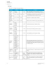
Name
Range
Step
Default
Description
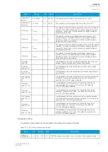
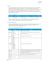
Use nominal
frequency
until
0…1800.000s
0.005s
0.100s
Defines how long the nominal frequency is used after the
tracking has started. This setting is only valid when the
"Sampling mode" setting is set to "Tracking" and when the
"Start behavior" is set to "First nominal or tracked".
Tracked f
channel A
0.000…75.000Hz 0.001Hz -
Displays the rough value of the tracked frequency in Channel
A.
Tracked f
channel B
0.000…75.000Hz 0.001Hz -
Displays the rough value of the tracked frequency in Channel
B.
Tracked f
channel C
0.000…75.000Hz 0.001Hz -
Displays the rough value of the tracked frequency in Channel
C.
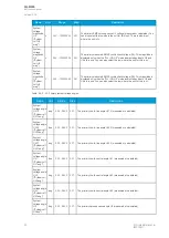
Alg f fast
0.000…75.000Hz 0.001Hz -
Frequency measurement built from tracked frequencies and
U4 voltage channel samples.
Alg f avg
0.000…75.000Hz 0.001Hz -
Averaged frequency measurement built from tracked
frequencies and U4 voltage channel samples.
System
measured
frequency
0: One f
measured
1: Two f
measured
2: Three f
measured
-
-
Displays the amount of frequencies that are measured.
f.atm.
Protections
0.000…75.000Hz 0.001Hz -
Frequency measurement value used by protection functions.
When frequency is not measurable this value returns to value
set to "System nominal frequency" parameter.
f.atm. Display
0.000…75.000Hz 0.001Hz -
Frequency measurement value used in display. When
frequency is not measurable this value is "0 Hz".
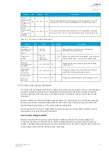
f
measurement
from
0: Not
measurable
1: Avg Ref 1
2: Avg Ref 2
3: Avg Ref 3
4: Track Ref 1
5: Track Ref 2
6: Track Ref 3
7: Fast Ref 1
8: Fast Ref 2
9: Fast Ref 3
-
-
Displays which reference is used for frequency measurement.
SS1.meas.frqs
0.000…75.000Hz 0.001Hz -
Displays frequency used by "system set" channel 1 and 2.
SS2.meas.frqs
SS1f
meas.from
0: Not
measurable
1: Fast Ref U3
2: Fast Ref U4
-
-
Displays which voltage channel frequency reference is used by
"system set" voltage channel.
SS2f
meas.from
0: Not
measurable
1: Fast Ref U4
-
-
Displays if U4 channel frequency reference is measurable or
not when the channel has been set to "system set" mode.
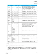
5.3 Protection functions
5.3.1 General properties of a protection function
The following flowchart describes the basic structure of any protection function. The basic structure is
composed of analog measurement values being compared to the pick-up values and operating time
characteristics.
A
AQ
Q-M255
-M255
Instruction manual
Version: 2.06
© Arcteq Relays Ltd
IM00020
51
Содержание AQ-M255
Страница 1: ...AQ M255 Motor protection IED Instruction manual...
Страница 2: ......
Страница 384: ...Figure 7 4 189 Example block scheme A AQ Q M255 M255 Instruction manual Version 2 06 382 Arcteq Relays Ltd IM00020...
Страница 405: ...Figure 8 14 211 Device installation A AQ Q M255 M255 Instruction manual Version 2 06 Arcteq Relays Ltd IM00020 403...

