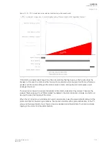
In the example above, problems may arise if, during the start-up of a motor, a short-circuit fault occurs
while the overcurrent stage is blocked. This may make the fault clearing take longer as the relay still
considers the situation part of starting. In this case the following logic can be used to prevent
prolonging of the fault clearing time during the start-up of the motor. The main benefit of this logic is
that there is no need to spend another protection stage for short-circuit faults: the one stage that is set
below the starting current of the motor can also be used for short-circuits and overcurrent faults. See
below for a more detailed description of the logic in question.
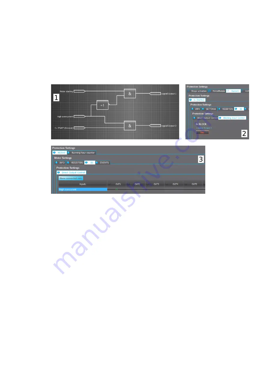
Figure. 5.3.17 - 100. Motor start up overcurrent control logic.
Picture 1 (upper left). During a start-up, the MST1_MOTSTART signal is connected to the
LOGIC_OUT1 signal with an AND gate, and to the MST1_HIGHOC signal (the function's high
overcurrent detection) with a NOT gate. The overcurrent (I>) stage is blocked when a motor starts, but
the blocking is released if a high overcurrent is detected during the start-up process. The user can
choose to combine the high overcurrent detection with the NOC1_START signal with an AND gate, and
use the LOGIC_OUT2 signal (for example) to change the active setting group of the I> function to
operate instantly.
Picture 2 (upper right). The LOGIC_OUT1 signal is connected to the I> blocking input (NOC1, first
stage overcurrent) function to block the stage in motor start-ups.
Picture 3 (bottom). The high overcurrent detection signal can also be directly connected to the output
relay. This way there is no need for extra logics for fault clearing control which makes fault clearing very
fast.
Alternatively, the user can release the tripping of the I> stage by letting the overcurrent function
operate on its set timer settings when a high overcurrent is detected. However, this requires that the
motor start detection current is set below the overcurrent stage.
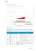
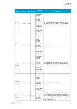
Settings and signals
The settings of the motor status monitoring function are mostly shared with other motor protection
functions in the device's motor module. The following table shows these other functions that also use
these settings.
A
AQ
Q-M255
-M255
Instruction manual
Version: 2.06
180
© Arcteq Relays Ltd
IM00020
Содержание AQ-M255
Страница 1: ...AQ M255 Motor protection IED Instruction manual...
Страница 2: ......
Страница 384: ...Figure 7 4 189 Example block scheme A AQ Q M255 M255 Instruction manual Version 2 06 382 Arcteq Relays Ltd IM00020...
Страница 405: ...Figure 8 14 211 Device installation A AQ Q M255 M255 Instruction manual Version 2 06 Arcteq Relays Ltd IM00020 403...


