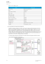
Setting up an RTD measurement, the user first needs to set the measurement module to scan the
wanted RTD elements. A multitude of Modbus-based modules are supported. Communication requires
bitrate, databits, parity, stopbits and Modbus I/O protocol to be set; this is done at
Communication
→
Connections. Once communication is set, the wanted channels are selected at Communication
→
Protocols
→
ModbusIO. Then the user selects the measurement module from the three (3) available
modules (A, B and C), as well as the poll address. Additionally, both the module type and the
polled channels need to be set. When using a thermocouple module, the thermo element type also
needs to be set for each of the measurement channels. Once these settings are done the RTDs are
ready for other functions.
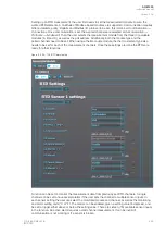
Figure. 5.3.24 - 139. RTD alarm setup.
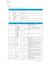
Function can be set to monitor the measurement data from previously set RTD channels. A single
channel can be set to have several alarms if the user sets the channel to multiple sensor inputs. In
each sensor setting the user can select the monitored module and channel, as well as the monitoring
and alarm setting units (°C or °F). The alarms can be enabled, given a setting value (in degrees), and
be set to trigger either above or below the setting value. There are sixteen (16) available sensor inputs
in the function. An active alarm requires a valid channel measurement. It can be invalid if
communication is not working or if a sensor is broken.
A
AQ
Q-M255
-M255
Instruction manual
Version: 2.06
© Arcteq Relays Ltd
IM00020
253
Содержание AQ-M255
Страница 1: ...AQ M255 Motor protection IED Instruction manual...
Страница 2: ......
Страница 384: ...Figure 7 4 189 Example block scheme A AQ Q M255 M255 Instruction manual Version 2 06 382 Arcteq Relays Ltd IM00020...
Страница 405: ...Figure 8 14 211 Device installation A AQ Q M255 M255 Instruction manual Version 2 06 Arcteq Relays Ltd IM00020 403...


