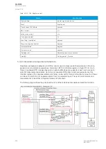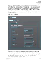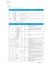
Name
Range
Step Default
Description
Temp.
reference
(tref)
k
amb
= 1.0
-60…500
deg
1
deg
15 deg
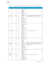
The temperature reference setting. The manufacturer's temperature
presumptions apply and the thermal correction factor is 1.00 (rated
temperature). For underground cables the set value for this is usually 15
̊
C
and for cables in the air it is usually 25
̊
C.
This setting is visible if "Ambient lin. or curve" is set to "Linear est."
Max.
ambient
temp.
0…500 deg
1
deg
45 deg
The maximum ambient temperature setting. If the measured temperature is
more than the maximum set temperature, the set correction factor for the
maximum temperature is used. This setting is visible if "Ambient lin. or curve" is
set to "Linear est."
k at max.
amb.
temp.
0.01…5.00 x
I
n
0.01
x I
n
1.00 x
I
n
The temperature correction factor for the maximum ambient temperature
setting. This setting is visible if "Ambient lin. or curve" is set to "Linear est."
Min.
ambient
temp.
-60…500
deg
1
deg
0 deg
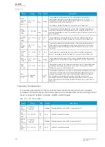
The minimum ambient temperature setting. If the measured temperature is
below the minimum set temperature, the set correction factor for minimum
temperature is used. This setting is visible if "Ambient lin. or curve" is set to
"Linear est."
k at min.
amb.
temp.
0.01…5.00 x
I
n
0.01
x I
n
1.00 x
I
n
The temperature correction factor for the minimum ambient temperature
setting. This setting is visible if "Ambient lin. or curve" is set to "Linear est."
Amb.
temp. ref.
1...10
-50.0…500.0
deg
0.1
deg
15 deg
The temperature reference points for the user-settable ambient temperature
coefficient curve. This setting is visible if "Ambient lin. or curve" is set to "Set
curve".
Amb.
temp.
k1...k10
0.01…5.00
1.00
0.01
The coefficient value for the temperature reference point. The coefficient and
temperature reference points must be set as pairs. This setting is visible if
"Ambient lin. or curve" is set to "Set curve".
Add
curvepoint
3…10
0: Not used
1: Used
-
0: Not
used
The selection of whether or not the curve temperature/coefficient pair is in use.
The minimum number to be set for the temperature/coefficient curve is two
pairs and the maximum is ten pairs. If the measured temperature is below
the set minimum temperature reference or above the maximum set
temperature reference, the used temperature coefficient is the first or last
value in the set curve. This setting is visible if "Ambient lin. or curve" is set to
"Set curve".
Operating characteristics
The operating characteristics of the machine thermal overload protection function are completely
controlled by the thermal image. The thermal capacity value calculated from the thermal image can set
the I/O controls with ALARM 1, ALARM 2, INHIBIT and TRIP signals.
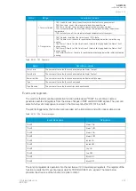
Table. 5.3.23 - 194. Pick-up settings.
Name
Range
Step Default
Description
Enable
TM>
Alarm 1
0: Disabled
1: Enabled
-
0:
Disabled Enabling/disabling the ALARM 1 signal and the I/O.
TM>
Alarm 1
level
0.0…150.0 %
0.1
%
40 %
ALARM 1 activation threshold.
Enable
TM>
Alarm 2
0: Disabled
1: Enabled
-
0:
Disabled Enabling/disabling the ALARM 2 signal and the IO.
TM>
Alarm 2
level
0.0…150.0 %
0.1
%
40 %
ALARM 2 activation threshold.
A
AQ
Q-M255
-M255
Instruction manual
Version: 2.06
248
© Arcteq Relays Ltd
IM00020
Содержание AQ-M255
Страница 1: ...AQ M255 Motor protection IED Instruction manual...
Страница 2: ......
Страница 384: ...Figure 7 4 189 Example block scheme A AQ Q M255 M255 Instruction manual Version 2 06 382 Arcteq Relays Ltd IM00020...
Страница 405: ...Figure 8 14 211 Device installation A AQ Q M255 M255 Instruction manual Version 2 06 Arcteq Relays Ltd IM00020 403...


