AMD2000 Series - Servo Drive - User Manual
52
DS619-0-00-0019 - Rev 0
ANCA Motion
6.9.12
du/dt Filter
The du/dt filters consist of inductors and capacitors in a low pass filter arrangement and their cut off frequency is
above the nominal switching frequency of the drive. Compared to Sine-wave filters they have lower L and C
values, thus they are cheaper and smaller, and have less voltage drop (approximately 0.5%). With a du/dt filter
the voltage wave form is still PWM shaped but the current is sinusoidal. The reduced performance of the du/dt
filter compared to the sinusoid filter makes it unsuitable for motor bearing current reduction and acoustic noise
reduction.
6.10
Motor Brake Connection
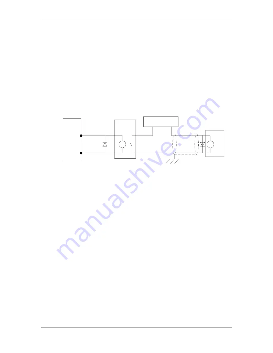
Some motors require the use of a brake to prevent motor movement when power is removed. The motor’s brake
must be wired up to a relay which is controlled by the 24V digital output 1 (DO1), on connector X4. The relay
must be wired with a protective fly-back diode as shown to prevent damage to the drive 0V supply.
IDN 33346 is the state of the motor brake control:
1: motor brake released
0: motor brake engaged
Relay:
Normally
Open
Motor
AMD2000
CN4/X4
0V
DO1
46 or 47
19
Separate Customer
24V DC supply
24V
0V
Figure 6-16: Motor Brake Interface Circuit
To engage the brake:
The motor is brought to rest under normal control;
The relay is deactivated, causing the brake to engage;
The drive is disabled, removing power from the motor.
To disengage the brake:
The drive is enabled;
The drive applies power to the motor to hold position under normal control;
The relay is activated, causing the brake to be disengaged.
It is sometimes necessary to include a small delay after the relay has been activated, before starting motion. This
delay allows time for the relay contacts to engage and the brake to release.
The 24V DC power supply for the brake must be a separate supply as brake wires often carry noise, and
generate a large voltage spike which may affect other devices connected to the brake supply. Do not use the
AMD2000 24V supply from X4 to power the brake. The separate 24 V DC supply used for the motor brake can
also be used to power the relay in the thermal switch circuit.
6.11
Motor Thermal Switch
Some motors provide thermal switch to
prevent the motor overheating. The motor’s thermal switch must be wired
up to a relay which generates a 24V digital input on connector X4. Any of digital inputs DI-01 to DI-08 may be
used and DI-01 is shown in
Figure 6-17
. The status of all digital inputs DI-01 to DI-08 can be monitored with IDN
33343 where bit 0 is the first digital input, bit 1 is the second digital input, etc. The IDN 33343 can be monitored
by an external CNC.


