Feature Configuration
ANCA Motion
DS619-0-00-0019 - Rev 0
135
10
Current loop integral gain scheduler
A current loop integral gain scheduler is provided in the AMD2000 to allow increased controller gain during
periods of small current command, where the gain characteristic decays drastically as signal frequency
increases.
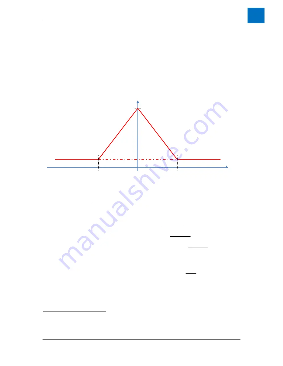
The current loop integral gain scheduler is enabled by setting IDN P-0-239 / 33007 to a value of 1. The
parameter P-0-241 / 33009 specifies the current loop integral time constant that will be used at zero current
command in place of the normal
q
-axis integral time (S-0-107 / 107). A smaller time constant results in a larger
gain, and vice-versa. The resulting gain is then interpolated as a function that adjusts the gain linearly when the
current hovers between the sym/- values of the variable described
as the “integral gain boost threshold,”
specified in IDN P-0-240 / 33008. See
Figure 10-24
for a graphical representation of the function. Note that the
resulting scheduler does not have to result in an increased gain near zero current, it could be just as easily
configured to decrease the gain near zero current; however, in most normal applications the desire will be to
increase the integral gain in such a circumstance.
Figure 10-24 Integral Gain Boost
Setting the Current and Torque limits
The minimum magnitude of
all
the current limits defined below will be applied by the motor control. With the
exception of the Variable Torque Limit , all the parameters listed below apply current limits on both positive and
negative current demands with the exception of the “Amplifier instantaneous current limit” which is applied to
detect current over limit and flag an error. The list of limits applied by the motor control, to either current or
torque demands, are:
Motor Peak Current (S-0-0109 / 109) defines the maximum
quadrature
current to which the drive is
rated.
Amplifier Peak Current (S-0-0110 / 110) specifies the maximum
quadrature
current rating of the drive.
This variable is configured automatically by the drive, and the user cannot change it.
Peak Torque Producing Current (P-0-0232 / 33000) defines the maximum
quadrature
current (and by
extension torque) which is suitable for the application.
It’s intent is to allow the user to specify a torque
(or force) limit on couplings or other mechanical features of the application that may be important, but
different, to the above motor and drive current limits. Although strictly speaking this limits current, it is
intended to apply to mechanical torques (or forces).
12
Peak Field Weakening Current (P-0-0926 / 33694) defines the maximum
direct
current which can be
commanded for field weakening. This is typically set to zero (0), and should not concern most users.
Variable Torque Control is a feature which allows the torque applied to the drive to be varied. This is
different to the limits defined above, in that different limits can be defined for positive and negative
torque.
This feature is controlled via the Variable Torque Control Word (P-0-0225 / 32993), where bit0
enables (ie. enable = 1) the Maximum Variable Torque Limit (P-0-0226 / 32994) and bit1 enables the
Minimum Variable Torque Limit (P-0-0227 / 32995).
12
Note that SoE treats the basic units for specifying current and torque quite separately, so the user needs to be aware that
current and torque may not simply be value equivalent, even if Kt=1. For example, torque may be represented in basic units of
0.01 N or N/m whereas current is in A. If this is the situation, then with Kt=1, a value of 100 reported for torque over SoE would
represent a value of 1 for quadrature current since the torque is being represented in units of cN/m or equivalently N/hm.
– P-0-240
K
i
P-0-240
S-0-106 / S-0-
107
S-0-106 / P-0-241
Q-axis Current
Command


