ing the cylinder head and taking it to a Yamaha deal-
ership or machine shop to have the valve seats
ground.
The following procedure is provided if you
choose to perform this task yourself.
A valve seat cutter set (consisting of 30°, 45° and
60° cutters and the appropriate handle) is needed.
These tool sets are available from a Yamaha dealer-
ship or from machine shop supply outlets. Follow
the manufacturer’s instruction when using the
cutters.
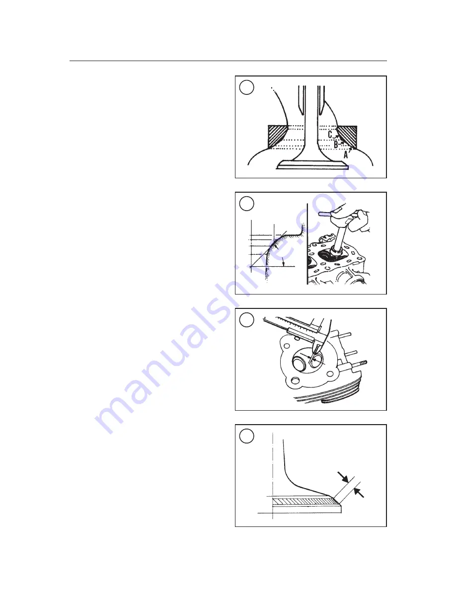
The valve seats for both the intake valves and ex-
haust valves are machined to the same angles. The
area below the contact surface (closest to the com-
bustion chamber) is cut to a 30° angle (A,
Figure
99
). The valve contact surface is cut to a 45° angle
(B,
Figure 99
). The area above the contact surface
(closest to the valve guide) is cut to a 60° angle (C,
Figure 99
).
1. Using the 45° cutter, descale and clean the valve
seat with one or two turns (
Figure 100
).
CAUTION
Measure the valve seat contact area in
the cylinder head (
Figure 101
) after
each cut to make sure the contact area
is correct and to prevent removing too
much material. If too much material is
removed, the cylinder head must be
replaced.
2. If the seat is still pitted or burned, turn the 45°
cutter additional turns until the surface is clean.
Avoid removing too much material from the cylin-
der head.
3. Remove the valve cutter and T-handle from the
cylinder head.
4. Use marking compound to inspect the valve
seat as described in
Valve Seat Inspection
in this
section.
5. If the contact area is centered on the valve face
but is too wide (
Figure 102
), use either the 30° or
the 60° cutter and remove a portion of the valve seat
material to narrow the contact area.
6. If the contact area is centered on the valve face
but is too narrow (
Figure 103
), use the 45° cutter
and remove a portion of the valve seat material to
increase the contact area.
7. If the contact area is too narrow and up close to
the valve head (
Figure 104
), first use the 30° cutter
118
CHAPTER FOUR
99
100
Rough seat
45°
101
102


