Page 88
WESMAR
HD800
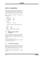
PART A: CALIBRATION
All HD800 sonars are calibrated at the WESMAR factory in
our test tank before shipping. However, WESMAR does rec-
ommend checking adjustments after installation. A sonar that
is correctly adjusted will give maximum range performance.
Before proceeding with calibration, set the sonar to the
following settings:
Menu
1:
1. Screen Mode
Full
3. Noise Filter
None
4.
Target
Filter
Off
Menu
3:
5. "A" Colors
Select 8
Use the Function Knob on the front panel and select:
Speed
1
Power
100%
Pulse 100%
TVG
Correct number for frequency
Threshold
3
1.0
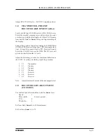
POSITIVE 5 VDC ADJUST
(CONSOLE)
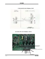
Connect the positive lead of a Digital Volt Meter (DVM),
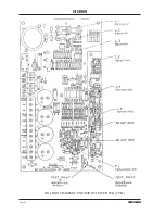
to the back side of R20 (see console drawing for location).
Connect the Negative Lead of the DVM to the TP1 or the
back panel.
Adjust RV2 for a Positive 5.1 VDC.
Note: This adjustment affects TVG Offset, next step. Both
adjustments must be done in order.
2.0
TVG OFFSET (CONSOLE)
Connect the positive lead of DVM to TVG output, blue wire
labeled "Y", located to the right back of the console circuit
board. Connect the negative lead to "TP1," receiver ground,
located right front of the console circuit board.
Set both Near and Far Gains of
Sonar A
to zero, counter-
clockwise.
Summary of Contents for HD800/110-10
Page 10: ...Page 10 WESMAR HD800...
Page 32: ...Page 32 WESMAR HD800 Section III INSTALLATION...
Page 64: ...Page 64 WESMAR HD800 HYDRAULIC HOIST ASSEMBLY A...
Page 65: ...Page 65 WESMAR INSTALLATION AND OPERATION HYDRAULIC HOIST ASSEMBLY B...
Page 74: ...Page 74 WESMAR HD800 M18 HOIST CONTROL CIRCUITRY THIS PAGE LEFT INTENTIONALLY BLANK...
Page 86: ...Page 86 WESMAR HD800...
Page 87: ...Page 87 WESMAR INSTALLATION AND OPERATION Section IV FIELD ADJUSTMENTS CALIBRATION...
Page 92: ...Page 92 WESMAR HD800 HD J BOX TRANSMIT PREAMP RECEIVER PCB T P R...


