Page 53
WESMAR
INSTALLATION AND OPERATION
9.1.8
Touch the +12VDC lead to
Terminal
2.
This will operate the hoist relays and power the
hoist motor, lowering the soundome.
When the bottom of the safety clamp is within 7.5
cm (3 inches) of the packing gland, remove the
wire from Terminal 2.
Move the hoist motor in small steps by tap-
ping the 12VDC wire to Terminal 2 until the
motor stops driving.
Do not let the safety clamp press into the packing
gland.
9.1.9
When the hoist stops, there must be at least
1.25 cm (.5 inches) between the safety clamp and
the packing gland.
The hoist should automatically stop lowering before
it reaches bottom.
If the safety clamp does not stop, or if it is less than
1.25 cm (.5 inches) above the packing gland, you
must reposition the top hoist clamp on the lead screw.
Check the "hoist down" light on the console. The
red light should be on.
To Reposition Top Hoist Clamp:
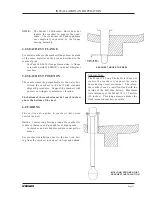
Determine how much space you need to add between
the safety clamp and packing gland.
Disconnect the lead screw from the hoist motor by
removing the bronze shear pin.
Rotate the lead screw counterclockwise (as viewed
from above) one complete turn for each 3.2 mm
(1/8 inch) of extra length needed.
Attach the lead screw to the hoist motor, using the
shear pin.
You will need to repeat the Hoist Operation Check
if you perform this or any other correction.
7.1.10
The 6-inch soundome must extend 15 cm
Summary of Contents for HD800/110-10
Page 10: ...Page 10 WESMAR HD800...
Page 32: ...Page 32 WESMAR HD800 Section III INSTALLATION...
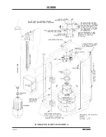
Page 64: ...Page 64 WESMAR HD800 HYDRAULIC HOIST ASSEMBLY A...
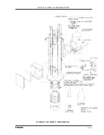
Page 65: ...Page 65 WESMAR INSTALLATION AND OPERATION HYDRAULIC HOIST ASSEMBLY B...
Page 74: ...Page 74 WESMAR HD800 M18 HOIST CONTROL CIRCUITRY THIS PAGE LEFT INTENTIONALLY BLANK...
Page 86: ...Page 86 WESMAR HD800...
Page 87: ...Page 87 WESMAR INSTALLATION AND OPERATION Section IV FIELD ADJUSTMENTS CALIBRATION...
Page 92: ...Page 92 WESMAR HD800 HD J BOX TRANSMIT PREAMP RECEIVER PCB T P R...


