Page 73
WESMAR
INSTALLATION AND OPERATION
AC HYDRAULIC HOIST WIRING
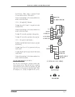
the DC motor. When voltage is present at 28 and
29, the contactor (relay) will energize.
Connect terminal lugs to the same numbered ter-
minals on the hoist board.
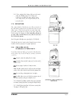
15.1.4 Wiring the DC Solenoid
Terminal Lugs 28, 29, and 31 are prewired to the
Solenoid Valve.
Connect terminal lugs to the same numbered ter-
minals on the hoist board.
Terminal 28 raises the soundome when positive.
Terminal 29 lowers the soundome when positive.
15.1.5 Wiring the Limit Switches
Both the top and bottom limit switches are prewired
at the factory.
Terminal lugs 25 and 27 are prewired to the top
limit switch.
Terminal lugs 25 and 26 are prewired to the bottom
limit switch.
Connect terminal lugs to the same numbered ter-
minals on the hoist board.
15.2 AC Hoist System (Part #749529)
The new AC Control Board is designed with a time
delay solenoid action. When the console is turned on
and the hoist switch is in the down position, the solid
state relay K1 will energize on the hoist board. When
K1 energizes, AC voltage is supplied to the AC mo-
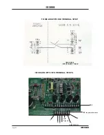
For 115 VAC
For 220 VAC
32
31
30
GROUND
AC SHIPS POWER
TB3
37
36
35
UP
DOWN
COMMON
AC MOTOR
AC MOTOR
TB2
S
S
M
TB1
UP
DOWN
27
26
25
UP LIMIT
SWITCH
DOWN LIMIT
SWITCH
Summary of Contents for HD800/110-10
Page 10: ...Page 10 WESMAR HD800...
Page 32: ...Page 32 WESMAR HD800 Section III INSTALLATION...
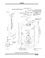
Page 64: ...Page 64 WESMAR HD800 HYDRAULIC HOIST ASSEMBLY A...
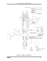
Page 65: ...Page 65 WESMAR INSTALLATION AND OPERATION HYDRAULIC HOIST ASSEMBLY B...
Page 74: ...Page 74 WESMAR HD800 M18 HOIST CONTROL CIRCUITRY THIS PAGE LEFT INTENTIONALLY BLANK...
Page 86: ...Page 86 WESMAR HD800...
Page 87: ...Page 87 WESMAR INSTALLATION AND OPERATION Section IV FIELD ADJUSTMENTS CALIBRATION...
Page 92: ...Page 92 WESMAR HD800 HD J BOX TRANSMIT PREAMP RECEIVER PCB T P R...


