2017717_b•en•2016-11-01
We reserve the right to make technical changes
55
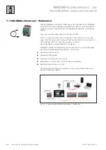
7.10 Sensor Nnside temperature / Humidity
7.10.1 Nnstalling inside temperature / Humidity sensor
The installation location is critical for obtaining correct measurements, as,
for example, installation above a heater or below a window will lead to
incorrect measurements. Do not expose the sensor to direct solar radiation
or drafts; this can also cause faulty measurements. The sensor should be
mounted at a height of approx. 1.5 m. The ventilation openings should not
be covered. Depending on how the connecting line is routed, it is fed into
the housing either from underneath (for surface-mounting) or from behind
(for flush-mounting). Proceed as follows in this case:
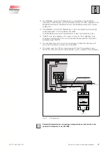
Open the housing
Pull the connecting line through the opening on the back panel of the
housing
Install the back panel of the housing with screw anchors and screws
Install the housing cover after the electrical connection has been made.
7.10.2 onnecting sensor Nnside temperature / Humidity
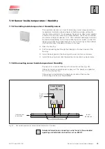
The sensor is connected directly to the four-wire bus line (
Fig. 33
).
It does not need a separate power supply unit. The power is supplied at
24 V DC via the bus line.
If the sensor is positioned at the beginning or end of the bus line,
a terminating resistor must be provided.
Sensor humidity
and
temperature inside
JY(St)Y 4×2×0.8 mm ∅
Bus A
Bus A
Bus B
Bus B
0 V
0 V
24 V DC
24 V DC
Status-
LED
Programming
button
X5
X6
0V 24V
Supply
WH YE
A B
RS 485
BK RD
from previous
bus device
to next
bus device
Fig. 33
Connection example for sensor Inside temperature / Humidity
Detailed information on connecting can be found in the associated
operating and installation instructions art. no. 890011.


