2017717_b•en•2016-11-01
We reserve the right to make technical changes
51
DC
24 V
230 V
AC
climabus
JY(St)Y 4×2×0.8 mm ∅
BK RD
From previous
bus device
Bus A
Bus B
0 V
To next
bus device
Bus A
Bus B
0 V
WH
X5:Input X6:RS485
Prog
X7:
0V 24V
A B
ID LED 15V 0V 15V 1 0V 15V
WAREMA climatronic®
Sensor Interface
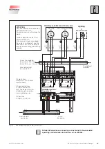
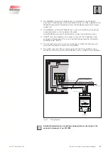
For the supply of the Sensor Interface we
recommend the mounting of a separate
power supply unit, depending on the
number and type of sensors connected to
the Sensor Interface.
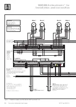
Fig. 27
Connection of the Sensor Interface to climabus and a separate power supply unit
1 2 3 4 5 6 7 8
ON
WAREMA climatronic®
Sensor Interface
24V 24V 0V 0V 15V 15V 0V 0V
15V 0V 24V 0V 24V 0V
15V 1 0V 15V 2 0V 15V 3 0V
15V 4 0V 15V 0V 15V 0V
X1: X2:
X3:
X4:
X5:Input X6:RS485
Prog
X7:
X8:
S2:
0V 24V
A B
ID LED 15V 0V 15V 1 0V 15V 2 0V
15V 3 0V 15V 4 0V 15V 0V
1 2 3 4 5 6 7 8
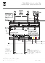
Terminal strip X1
Reserve terminals for
the sensor power
supply
Terminal strip X2
Reserve terminals for
the sensor power
supply
Terminal strip X3
Connection of the
photo 1-3 sensor
Terminal strip X4
Connection of the
photo 4 sensor,
global radiation sensor
and dawn/susk sensor
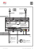
Terminals X6
Connection to
the WAREMA
climabus
Terminal strip X7
Connection of the
radio clock and
wind 1-2 sensors
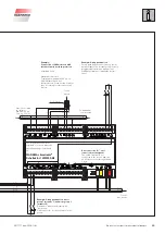
Terminal strip X8
Connection of the
wind 3-4 and
wind direction sensors
Encoding switch S2
Setting of the sensor
input characteristic
Terminals X5
Connection of
the power
supply
24 V DC
Service-LED
Display of the
incoming
DCF77 signals
Service push
button
for logging onto
the WAREMA
climatronic
®
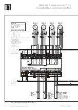
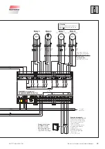
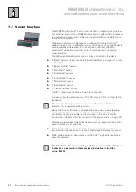
Fig. 28
All connections at a glance


