2017717_b•en•2016-11-01
We reserve the right to make technical changes
53
X5:Input X6:RS485
Prog
X7:
0V 24V
A B
ID LED
P 25 26 27 28 29 5V
DC
24 V
230 V
AC
climabus
BK RD
From previous
bus device
Bus A
Bus B
0 V
To next
bus device
Bus A
Bus B
0 V
WAREMA climatronic®
Tableau Interface M
WH
For the supply of the Tableau Interface M
we recommend the mounting of a
separate power supply unit, depending on
the line length and the number of devices.
JY(St)Y 4×2×0.8 mm ø
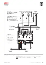
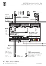
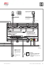
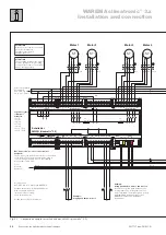
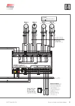
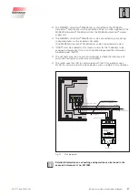
Fig. 30
Connection of the Tableau Interface M to climabus and a separate power supply unit
Slave-Bus
JY(St)Y 2×2×0.8 mm ∅
WH YE
BU OG
1 2 3 4
ON
X10:Input X11:RS485
X3: |
|
|
|
0V 24V A1 B1 LED S2:Adr.
P 17 18 19 20
1 2 3 4
ON
X10:Output X11:RS485
S2:Adr. P |
|
|
|
|
24V 0V B1 A1 S L A V E
X2: 1 2 3 4 5
Slave-Bus
last
JY(St)Y 2×2×0.8 mm ∅
WH YE
BU OG
1 2 3 4
ON
X10:Input X11:RS485
X3: |
|
|
|
0V 24V A1 B1 LED S2:Adr.
P 17 18 19 20
Tableau Interface S
(Adress 1)
Tableau Interface S
(Adress 4)
Tableau Interface M
(Adress 1)
YE WH
OG BU
*
Maximum overall length of the RS485 bus is
1200 m.
The ends of the bus line must be terminated with a
120 Ω resistor. To do this, insert the enclosed
resistors into the bus terminals.
(The output of the Tableau Interface M can remain
open if no Slave-Bus is used.)
At least 20 V must still be supplied to the device at
the end of the bus line.
Terminating resistor 120 Ω
Terminating resistor120 Ω
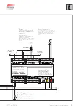
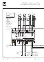
Fig. 31
Connection of Tableau Interfaces S

