2017717_b•en•2016-11-01
We reserve the right to make technical changes
41
WAREMA climatronic®
Schaltaktor 4M
F1 6,3
AT
H
F2 6,3
AT
H
WAREMA climatronic®
Schaltaktor 6M
F1 6,3
AT
H
F2 6,3
AT
H
F3 6,3
AT
H
L
N
PE
1
3
2
BU BK BN
GNYE
M∼
Motor 1
Sun shading system
1
3
2
BU BK BN
GNYE
M∼
Motor 2
Sun shading system
N
PE
N
PE
1
3
2
BU BK BN
GNYE
M∼
Motor 3
Sun shading system
1
3
2
BU BK BN
GNYE
M∼
Motor 4
Window 230 V
N
PE
N
PE
Lighting
1
3
2
BU BK BN
GNYE
M∼
Motor 5
Sun shading system
N
PE
H1
H2
1
3
2
BU BK BN
GNYE
M∼
Motor 6
Sun shading system
1
3
2
BU BK BN
GNYE
M∼
Motor 7
Sun shading system
N
PE
N
PE
1
3
2
BU BK BN
GNYE
M∼
Motor 8
Sun shading system
1
3
2
BU BK BN
GNYE
M∼
Motor 9
Sun shading system
N
PE
N
PE
N
CLOSE
OPEN
Power line provided
by customer
230 V AC, 50 Hz,
16 A, 3 x 1.5 mm
2
ATTENTION:
Only one motor can be connected
per motor terminal set.
Parallel connection will
damage the motor.
The total power (of all 4 outputs)
per fuse must not exceed 1000 VA.
All motor lines
H05-RR-F 4 G 0.75 black
type WAREMA
All push button lines
JY(St)Y 2x2x0.8 mm
Max. line length 200 m for
interference-proof routing,
use a twisted pair line.
All bus lines
JY(St)Y 4×2×0.8 mm
L
N
PE
L
N
PE
Example: Group push
button, motor 7 and motor 8
Connection of group push
buttons at the locking inputs.
The locking function is no
longer available. The relevant
group is freely programmable
within an actuator (see
WAREMA climatronic
®
installation instructions)
Example: group
push button, motor
5 and motor 6
Groups are built for
all actuators by
"jumpering".
Only connect In+ for
the actuators in the
group.
Only connect P for
the actuators in the
group.
Example:
Single push
button,
motor 1
S1
From
previous
bus device
Bus A
Bus B
0 V
24 V DC
To next
bus device
Bus A
Bus B
0 V
24 V DC
Power supply
unit
24 V DC
Zuleitung
bauseitig
230 V AC, 50 Hz
3 x 1,5 mm
2
Bus A
Bus B
0 V
Bus A
Bus B
0 V
Example:
Group push
button, motor 2
and motor 3
Groups are built
by means of
"jumpering"
Example: Further power
supply unit 24 V DC
If the power from one power
supply unit is not sufficient, an
additional power supply unit is
needed. Subdivide the 24 V
wire into subsections. Do not
operate power supply units in
parallel. The 0-V wire must
always be connected through
all components.
Example: Interlocking
via window contact
Operation is enabled
when the window is shut.
This function must be
programmed accordingly.
P
P
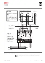
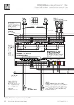
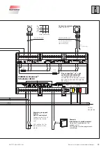
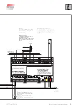
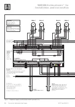
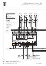
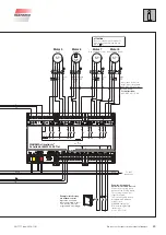
Fig. 22
Connection example for switch actuators 4M and 6M


