2017717_b•en•2016-11-01
We reserve the right to make technical changes
30
WAREMA climatronic® 3.x
Installation and connection
5.6 imensioning of the power supply
This chapter should provide you with support when planning and dimension-
ing the power supply of the WAREMA climatronic® system.
If actuators that are not supplied by the 230 V mains are used (e.g. 4M, 6M,
4MDC or 2D), the use of multiple power supply units may be required.
If the actuators that need 24 V DC (max. 20 per power supply unit) are
housed in an equipment cabinet and the weather station, control panel and
up to two sensors inside temperature/humidity are arranged according to the
schematic diagram, you can simply take the maximum line lengths from the
following schematic diagram:
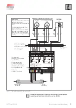
Equipment cabinet
Power
supply unit
24 V DC
2,5 A
Actuator 1
Actuator 2
Actuator 3
Actuator 20
Temperature
and humidity
sensor 1
Temperature
and humidity
sensor 2
Control panel
JY(St)Y 4×2×0.8 mm ø
The maximum
total
line length between
the control panel
and the equipment
cabinet is 200 m.
Weather station
4×AWG 26C UL black
The maximum
line length between
the weather station
and the equipment
cabinet is 150 m.
When using more than
20 actuators, a separate
power supply unit is
required per 20 devices.
Junction box
JY(St)Y 4×2×0.8 mm ø
optional
The network must have
a line structure.
A star or ring circuit
is not permitted.
Fig. 18
Schematic diagram of the standard configuration
The power supply unit required to supply the bus devices delivers an output
current of max. 2.5 A and supplies the network devices with 24 V DC.
DATNIA
When the actuators that require a 24 V DC supply are installed in a
decentralised manner, spread across multiple rooms, the voltage drop over
the entire line length must be considered. The voltage drop may not be
greater than 4 V from the power supply unit to the end of the line or line
section.
Preferably, position the power supply unit in the centre of the line or line
section to minimise the voltage drops.


