2017717_b•en•2016-11-01
We reserve the right to make technical changes
37
7.5 Switch actuator 4M230 LS2 Low DP/EGN
The switch actuator 4M230 LS2 Low (REG and AP) is an electronic control
device to control up to 4 sun shading and window drives.
The switch actuator is especially suitable for controlling external venetian
blinds with 2 lower limit switches. With the 4M230 LS2 Low, an external vene-
tian blind with 2 lower limit switches can be moved with opened slats to the
lower limit switch and only tilts the slats then.
If a DOWN command is issued from the local operating element, the external
venetian blind moves at an angle set by the mechanics and that cannot be
changed to the first lower limit switch and stays in this position. The external
venetian blind moves to the second lower limit switch and the slats close
only when a second DOWN command is issued.
If a second DOWN command is triggered during the downward movement
of the external venetian blind following the first move command, the
sun shading product first moves to the first lower limit switch and then
automatically moves to the second lower limit switch. The slats close once
this position is reached.
If the command is issued from a central control unit, the product can move
directly either to an intermediate position (e.g. 50%) or the second lower limit
switch.
Each actuator uses three relays to control the motor:
one relay for raising the sun shading product, a second relay for the
downward movement to lower limit switch 1 and the third relay for the
downward movement to lower limit switch 2.
5-wire motor lines must be used to connect these kind of external venetian
blinds.
The switch actuator and its downstream power consumer are supplied
with 230 V AC. The connected products are controlled via the WAREMA
climatronic®; an on-site control device with suitable operating elements is
also a possibility.
To operate the switch actuator 4M230 LS2 Low, a WAR MA climatronic®
3.3 control panel or newer is needed. If you have an older control panel,
contact WAR MA for more information.
To prevent damage to the connected motors, the default settings are such
that only one relay is activated at a time and connected single push buttons
operate in dead man's mode. Group buttons and locking contacts are
functional after the actuator has been commissioned.
Install the actuator as described in
chapter 4.4 on page 15
.
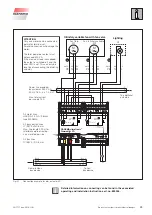
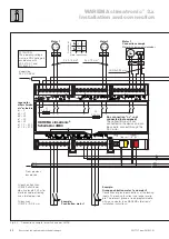
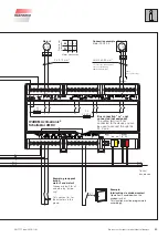
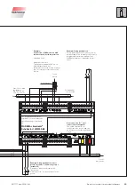
Use the
wiring diagram on page 48
to connect the actuator.
Detailed information on connecting can be found in the associated
installation instructions art. no. 2015626.


