background image

Operations

115

© 2006 Vision Engraving Systems

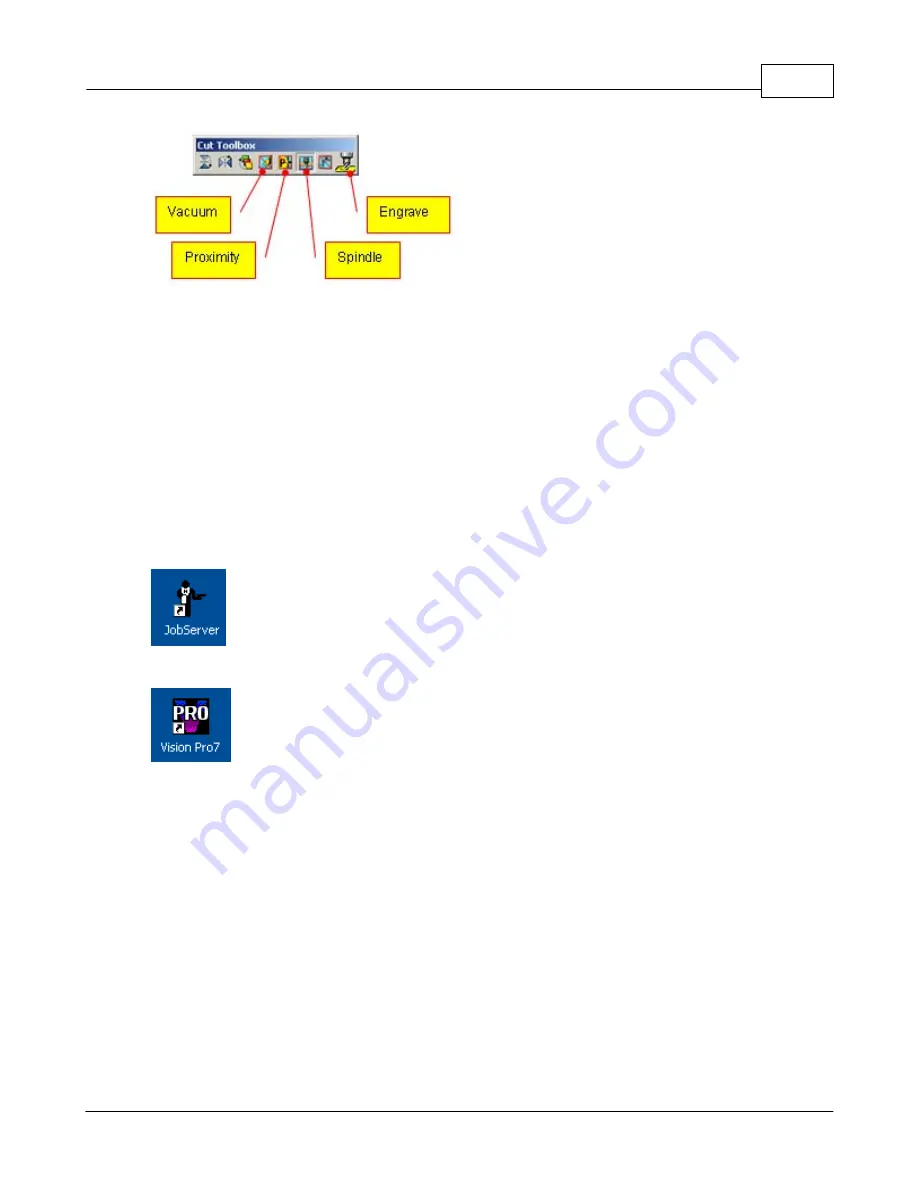
Click the Engrave icon.  After a brief moment, the LCD screen on the hand help pendant will
display "Press Start to Go".
On the first luggage tag, it is recommended to do a "Dry Run" with the red pointer to ensure
the correct positioning of the text on the pen.  Press the 

Shift

 button on the hand held

pendant and then press 

Start

.  The machine will run the job with the red pointer.  You can

verify that the engraving will be in the correct position.
If it is in the correct position, you can now engrave the pen.  Press the 

Start

 button.  The

LCD will display "Press Start to Go".  Press the 

Start

 button and the luggage tag will be

engraved.

Lesson 5 - Engraving Rings and Bracelets

Make sure the MaxPro machine is powered on, the Goto Home button has been pressed
and the Job Server program has been started by clicking on the Job Server icon on the
Windows desktop.

Start Vision Pro by clicking the Vision Pro icon from the desktop in Windows.

Hardware setup

Press the “Rotary Axis” button and the LCD will display a choice: “1 – Standard mode” and
“2 – Ring mode”.  Enter the number “2” and press enter. 

On the next screen enter either the outside or inside diameter of the ring depending on what
side will be engraved using the digital calipers provided.  Press “Enter” to complete.  After
pressing “Enter” the machine will move to the center of the vice automatically.

Press Set Surface and then press the Enter button.

Mounting the ring attachment

The ring attachment mounts on the gearbox side of the vice (left side).  Before sliding the
ring attachment over the drive shaft, locate the three mounting holes.  Align the set screws
on the ring attachment with these holes and slide it on.  Secure the screws with the included
T-Handle wrench.  Turn the ring attachment by pressing the left or right arrow keys to reach
all the screws.

Summary of Contents for MaxPro

Page 1: ...Operations Manual Vision Engraving Routing Systems 17621 N Black Canyon Hwy Phoenix AZ 85023 www visionengravers com Vision MaxPro ...

Page 2: ... to these trademarks While every precaution has been taken in the preparation of this document the publisher and the author assume no responsibility for errors or omissions or for damages resulting from the use of information contained in this document or from the use of programs and source code that may accompany it In no event shall the publisher and the author be liable for any loss of profit o...

Page 3: ...tware 20 Installing Job Server 31 Installing Vision Pro Vision Pro LT 40 Configuring Vision Pro Vision Pro LT 46 Table setup 46 T Slot table 48 Vice 51 Rotary 53 Using Water 53 Filling the Reservoir 54 Adjusting the flow Part III Operations 58 58 Starting the Job Server 60 Hand Held Pendant 60 Buttons 68 LCD Display 76 Operations and Lessons 76 Selecing machine drivers 79 Holding Flat Items with t...

Page 4: ...canning and Graphic editing 171 Creating Custom Vision Pro Drivers Part IV Maintenance 180 180 Lubrication 184 Changing the Motor Belt 185 Draining and Cleaning the Water Resevoir 186 Cleaning the vice rail and lead screw Part V Troubleshooting 188 188 Job Server Index 197 ...

Page 5: ...Chapter I ...

Page 6: ...avoid electric shock or equipment damage ensure that the control unit is connected to the appropriate electrical source as noted in the installation procedures ØNever operate the equipment with damaged or frayed power cords loose connections or exposed extension cords where someone can step on the cord and create a tripping hazard ØBe sure to hold the plug not the cord when disconnecting the contr...

Page 7: ...s screws on the sides Remove the two wood pieces that are screwed into the base of the crate The machine can now be removed In the crate will be a cardboard box with all of the machine accessories including this manual Open the accessory box and the following items should be included Ø1 Hand held pendant Ø1 Vision warranty card Ø1 This MaxPro manual Ø1 Vision All Products CD Ø1 Vision Pro or Visio...

Page 8: ...5 tip Ø1 Rotating diamond cutter 015 tip Ø2 Burnishing Adaptors Ø1 Universal Pin Fixture Ø1 Adjustable Pen Fixture Ø1 Universal Clamping Bars w Medallion Holder Ø1 T Handle Allen Wrench 3 32 Ø1 Gold Rub n Buff Ø1 White Rub n Buff Ø1 Silver Rub n Buff Step 2 Prepare a clean level surface to put the engraving machine on Carefully lift the machine out of the crate and place it on the table Step 3 Aft...

Page 9: ...eter x 12 tall 152 mm x 304mm Work holding vice Self centering vice with pins for holding various clamps Spindle speed 3 000 to 16 000 adjustable RPM Tilt angle 15 degrees maximum Power requirements 110 or 220 volts 10 amp Laser pointer 640 nanometers 5 milliwatts Water system Self contained recirculating pump for engraving glass Overall Dimensions 26 1 2 Tall x 28 Wide x 28 Deep 673 mm x 711 mm x...

Page 10: ...Vision MaxPro 6 2006 Vision Engraving Systems Shipping dimensions 41 x 33 x 39 5 1041mm x 838mm x 1003mm Machine weight 150 lbs Shipping weight 325 lbs ...

Page 11: ...Chapter II ...

Page 12: ...2 1 below Figure 2 1 The table cable connection box Plug the 25 pin cable into the table cable connection box as shown in figure 2 1 above The connector is labeled number 1 Make sure to tighten the two table cable tightening screws shown Caution Do not over tighten these screws Connect the remaining cables per figure 2 2 below A description of each connection is below Figure 2 2 The Vision Serial ...

Page 13: ...MaxPro to your computers serial port Note This is only used if you are NOT using the network connection on the MaxPro 4 Looking from the back side of the machine plug in the large cable from the right upright into the plug labeled 4 in figure 2 2 This is used for the rotary axis motor and vice motor Make sure to tighten both screws in the plug securely 5 Connect the 25 pin cable to the plug labele...

Page 14: ...rk cable to the network plug on the back of the MaxPro The other end of the network cable connects in one of two ways Direct to the PC If you are connecting the MaxPro directly to a PC and not through a network server please attach the supplied network crossover adaptor to the end of the network cable Then plug the adaptor directly into the network connection in the back of your PC The IP address ...

Page 15: ...ecify IP Press the Enter button on the controller 6 Press the EXIT button on the controller to specify an IP address 7 Using the number pad on the pendant type 192 and press Enter 8 Type 168 and then Enter 9 Type 5 and then Enter 10 Type 101 and then Enter 11 The Enter NetMask screen will show on the LCD screen Type 255 and then Enter 12 Type 255 and then Enter 13 Type 255 and then Enter 14 Type 0...

Page 16: ...are different depending on which version of the Windows operating system you are using Please follow the instructions below for the correct version of Windows is on your PC Windows XP 1 If there is a My Network Places icon on your main Windows screen go to step 3 below 2 If there is no My Network Places icon on your main Windows screen click on the Start button at the lower left corner of the Wind...

Page 17: ...Configuration 13 2006 Vision Engraving Systems 5 Highlight the Internet Protocol TCP IP and click on Properties ...

Page 18: ...Vision MaxPro 14 2006 Vision Engraving Systems 6 Select Use the following IP address Enter the numbers shown below for the IP address and Subnet mask ...

Page 19: ... Engraving Systems 7 Click OK and the click Close Windows 2000 1 Right click on My Network Places from the Windows desktop and go to Properties 2 Right mouse click on the Network Connection in the right side and select Properties ...

Page 20: ...Vision MaxPro 16 2006 Vision Engraving Systems 3 Highlight the Internet Protocol TCP IP and click on Properties ...

Page 21: ...Configuration 17 2006 Vision Engraving Systems 4 Select Use the following IP address Enter the numbers shown below for the IP address and Subnet mask ...

Page 22: ...Vision MaxPro 18 2006 Vision Engraving Systems 5 Click OK and the click Close Windows 98 1 Right click on Network Neighborhood and go to Properties 2 Highlight TCP IP and click on Properties ...

Page 23: ...Configuration 19 2006 Vision Engraving Systems 3 Click on the IP Address tab ...

Page 24: ...Vision controller To install the job server program follow the steps below IMPORTANT You must have administrative privileges on the PC that you are installing the Vision Job Server program on If not the program will not install properly 1 Insert the Vision All Products CD into the PC 2 The following screen should appear If not click on Start Run and then type in d SetupV7 exe where d is the letter...

Page 25: ...Configuration 21 2006 Vision Engraving Systems 3 Select Job Server Series 3 Controller and MaxPro and click Next 4 From the Welcome screen click Next ...

Page 26: ...Vision MaxPro 22 2006 Vision Engraving Systems 5 6 Select the default destination folder or select a different one and click Next ...

Page 27: ...onfiguration 23 2006 Vision Engraving Systems 7 Select the installation type Most users will select typical and click Next 8 Select the default program file name or select a different one and click Next ...

Page 28: ...Vision MaxPro 24 2006 Vision Engraving Systems 9 Click Next from the start copying files screen 10 Select OK from the information screen ...

Page 29: ...ing Systems 11 Make sure that the MaxPro machine is powered on and select Add 12 NOTE When using Windows XP with service pack 2 or higher the following message may appear the first time that a machine is added Select Unblock to continue ...

Page 30: ...al cable skip to step 17 14 The MaxPro should be detected through the network connection and shown in the Connection Name above If you have multiple Vision systems or MaxPro machines connected on your network or PC multiple machines will be shown in the screen below You can have an unlimited amount of machines connected to one PC Click Finish ...

Page 31: ...Configuration 27 2006 Vision Engraving Systems 15 Select Close 16 Select Finish The Job Server program is now installed Please skip items 17 through 23 and proceed to the next section ...

Page 32: ...n MaxPro 28 2006 Vision Engraving Systems 17 If the MaxPro is connected to a serial port instead of a network continue here 18 Select Don t detect my Machine Tool I will select it from a list and click Next ...

Page 33: ...Configuration 29 2006 Vision Engraving Systems 19 Select Default Machine and click Next 20 Enter a name for your MaxPro and select the Communications Port that the machine is connected to Click Next ...

Page 34: ...Vision MaxPro 30 2006 Vision Engraving Systems 21 Click Finish 22 Select Close 23 Select Finish The Job Server program is now installed ...

Page 35: ...he Vision Pro and Vision Pro LT software includes a hardware security device called a dongle This can either be a USB type or parallel port type The standard is a USB type which plugs into a USB port in the PC Important Do not plug the USB type dongle into the PC until the Vision Pro Vision Pro LT software has been installed 1 Insert the Vision All Products CD into the PC 2 The following screen sh...

Page 36: ...ion Engraving Systems 4 If this is a new installation please make sure that the Engraving Fonts is selected in the Select Files screen below and click NEXT 5 Use the default folder name or select a different one and click Next ...

Page 37: ...on Pro LT will be installed in and click OK 7 Select the type of Vision Pro Vision Pro LT security device included with the software package The standard is a USB type security device Click Next 8 Select the type of Vision Pro software to be installed This is typically either Vision Pro or ...

Page 38: ...ems Vision Pro LT Click Next 9 Select Next on the welcome screen 10 Read the license agreement and click I accept the terms of the license agreement and click Next to accept Please note that you must agree with the license agreement to continue ...

Page 39: ...Configuration 35 2006 Vision Engraving Systems 1 Select the default destination folder or select a different one and click Next 11 Select Full Installation ...

Page 40: ...n MaxPro 36 2006 Vision Engraving Systems 12 Select the default program file name or select a different one and click Next 13 Select Yes I would like to upgrade or install new cutting devices and click Next ...

Page 41: ...n MaxPro drivers on the left side of the screen Putting a check mark in the Vision Max Pro on the left side of the screen will install all of the MaxPro drivers on the right side of the screen Select Next 15 Click Continue to install the Vision Pro Vision Pro LT fonts ...

Page 42: ... to continue 17 Click OK to continue 18 Click Yes if you would like to install the 1100 outline fonts or No if you would not like to install them These are not necessary fonts unless you require an outline font They can be installed at a later time if required ...

Page 43: ...Vision Engraving Systems 19 Click OK to complete the font installation 20 Select Yes I want to restart my computer now and click Finish 21 The computer will now restart Vision Pro or Vision Pro LT is now installed completely ...

Page 44: ...his document Please follow the instructions for the configuration of your machine Configuration 1 The MaxPro network cable connects directly to the PC There is no external network involved In this configuration no Vision Pro software configuration is required Configuration 2 The MaxPro network cable connects to a network The PC network cable connects to the same network but not directly to the Max...

Page 45: ... Click the Setup icon to the right of the selected driver With the MaxPro Inside Ring driver highlighted click the Port tab at the top of the screen Change the Port Location to TCPIP raw by clicking the down arrow to the right of the port location ...

Page 46: ...ress of the MaxPro that was given to the machine in the Configuring the PC section of this document This will typically be assigned by a network administrator The value in the Port window will always be set to 23 Click the Apply button Next change the Port Location back to File and click Apply ...

Page 47: ...r that was done for the MaxPro Inside Ring driver Do this for the remaining four drivers and then click OK two times Configuration 3 The MaxPro connects to the PC through a serial cable In this configuration start Vision Pro by clicking on the desktop Vision Pro icon Click OK on the plate size screen that appears Go to the Engrave Engraving Defaults menu item The screen below will appear ...

Page 48: ...Vision MaxPro 44 2006 Vision Engraving Systems Click the Setup icon to the right of the selected driver With the MaxPro Inside Ring driver highlighted click the Port tab ...

Page 49: ...e the Port Location to COM1 clicking the down arrow to the right of the port location The COM port number is the serial port number on your PC If the machine is connected to a different COM port such as serial port 3 select COM3 in the Port Location box ...

Page 50: ...lat items such as plaques and name tags The quick lock vice included with the machine can be used to hold smaller items If items are larger in size either double sided tape or Multi Mat material can be used to hold the part down to the table More information on the Multi Mat material can be found in the Vision accessory catalog or online at www visionengravers com under the accessories web page Th...

Page 51: ...able The T Slot table can now be taken off Please note that once the screws are removed the table must be removed by pulling up evenly on the table as it is resting on four pins for alignment Be careful not to lose the pins To re install the T Slot table open or close the vice until the pins in the top of the vice line up with the holes in the T Slot table Insert and tighten the four Allen head sc...

Page 52: ...used A selection of fixtures are available for use with the vice More information on the available fixtures can be found in the Vision accessory catalog or online at www visionengravers com Any of the fixtures available slide over the two pins on each of the vice uprights Pictures of various fixtures and clamping methods are shown below Engraving a pen with the pen medallion fixture ...

Page 53: ...Configuration 49 2006 Vision Engraving Systems Engraving a medallion with the seal fixture Engraving a lighter with the universal pin fixture Engraving a shape with the universal pin fixture ...

Page 54: ...ce can also be automatically opened or closed To do this power the machine on Wait approximately 10 seconds for the machine to initialize and press the Goto Home button Next press and release the Shift button on the hand held pendant The green light on the button will illuminate Then press the X left or X right arrow The left arrow opens the vice and the right arrow closes the vice ...

Page 55: ...anual This will allow the rotary axis to be used The machine needs to be put into rotary axis mode To do this power the machine on Wait approximately 10 seconds for the machine to initialize and press the Goto Home button Press the Rotary Axis button on the pendant The LCD will display the screen below Press 1 and then ENTER The following screen will appear ...

Page 56: ...ould like to engrave Use a ruler to measure the distance across the round item per the picture below The spindle will move to the center of the vice and the light on the rotary axis button will be illuminated Insert the tapered cone into the left side of the vice per the picture below ...

Page 57: ... engraved evenly with the lines in the blue material on the right cone Tighten the vice with the tightening wheel or by pressing the Shift and then X left or X right button on the pendant until the vice it tight Using Water Filling the Reservoir To engrave into glass or ceramics the water reservoir must be filled with water The water can then be turned on to flow over the glass or ceramic material...

Page 58: ...s to be adjusted to obtain the correct flow the valve may need to me adjusted Locate the water flow valve per the picture below It is located just below and behind the center of the water collection tray that is at the base of the vice Remove the T Slot table The machine needs to be put into rotary axis mode To do this power the machine on Wait approximately 10 seconds for the machine to initializ...

Page 59: ... on the spindle Press the Y Down button until the cursor is flashing on Pump Press the Shift button The light on the button will illuminate Press the Enter button This will turn the pump on The water will start to flow out of the water nose cone at the spindle If there is no water flowing the water flow is too slow or too fast turn the thumbscrew on the water flow valve shown below Turning it cloc...

Page 60: ......

Page 61: ...Chapter III ...

Page 62: ...the MaxPro machine To start the Job Server go to the Start Programs Vision Machine Tools menu and select Job Server NOTE When using Windows XP with service pack 2 or higher the following message may appear the first time that the Job Server is started Select Unblock to continue The screen below will appear for a few seconds and then it will go away ...

Page 63: ...he left in the picture below Note You can create a shortcut on the Windows desktop so that you do not need to go to the Windows program group run the job server To do this follow the steps below 1 While the Vision job server is running right mouse click on the icon in the Windows system tray This is the icon all the way to the left in the picture above Click Create Shortcut ...

Page 64: ... and select Desktop Click OK The Job Server can now be started from clicking the MaxPro icon from the Windows desktop Hand Held Pendant Buttons The Vision hand held pendant is the interface between the computer and the engraver It allows you to control the way the machine engraves ...

Page 65: ...d that the table will run at while the cutter is in the down position This number is in inches per second or millimeters per second depending on the setup of the machine With the arrow pointing to the feed number on the LCD turning the knob on the pendant clockwise or counterclockwise will increase or decrease the speed The feed number will display the change The ZSpd number shows the speed that t...

Page 66: ...the Speed Adjust button on the pendant which will toggle the arrow between Feed ZSpd and RPM The Buttons There are 15 buttons on the hand held pendant START Button The light above the Start Button will be off when the controller is ready to have a job sent to it The light will flash when there is a job ready to be engraved in the controller Also the LCD screen will show Press Start to Go when a jo...

Page 67: ...op the job You will get a prompt on the LCD screen to either continue or cancel the job The red light on the pause button will illuminate to show the job is paused Press the Start Button to resume engraving TIP When a job is in the controller you can press the pause button before pressing the start button This will cause the machine to move to the starting engraving position and pause You can then...

Page 68: ...ast The speed that the X and Y jog at is determined by this Press the Shift and Speed Adjust buttons until the LCD shows Jog Slow to fine tune the jog position JOG MODE Button This button is used to change the functionality of the Up and Down jog buttons When the jog mode button is pressed the light on the button will illuminate The Up and Down jog buttons now move the spindle up and down Pressing...

Page 69: ...ace Button is only used when the proximity sensor is off You can use the XY job Buttons to move the cutter out over the material Press the Set Surface button and then use the Up and Down jog buttons to move the cutter to the surface of the material and then press Enter The spindle will lift to the default Z lift height and the surface will be set ROTARY AXIS Button This button allows for a round i...

Page 70: ... knob will adjust the speed that the machine engraves at You will see an arrow pointing to the Feed rate on the LCD per the picture below Pressing the Speed Adjust button will move the arrow to the Z Speed on the LCD per the picture below Now turning the speed knob will adjust the speed that the Z axis travels at Pressing the Speed Adjust button again will move the arrow to the RPM on the LCD per ...

Page 71: ...ft arrow down This sequence closes the vice automatically while holding the right arrow down This sequence will change the jog speed shown on the LCD screen from Medium to slow to Fast The speed that the X Y and Z jog at is determined by this Press the Shift and Speed Adjust buttons until the LCD shows Jog Slow to fine tune the jog position This sequence turns the red pointer on and off This seque...

Page 72: ...ssing the Menu button on the pendant will display different options and features of the MaxPro machine The first time that the Menu button is pressed the screen below will appear Pressing the Y down button will move the cursor down one line at a time Once the last line is highlighted the Y down button will scroll to the menu below The next menu is shown below Each menu item in the LCD screen will ...

Page 73: ...he pendant will toggle the Prox between On and Off When the Prox is required while engraving this should be set to On When the Prox is not required this should be set to Off Press the Exit button to return to the main menu Access Jobs Pressing the Y down arrow again will display the screen below The cursor will flash on Access Jobs The Access Jobs feature is used to re engrave jobs that have been ...

Page 74: ...t the Display Job Time menu item and press Enter to get a read out on your LCD of the amount of time it took to engrave Home Positions This menu will display a second menu with more options regarding home positions shown below Set Home This menu item is used to set an alternate home position Use the Jog Buttons to move the spindle to the point you would like to set as an alternative home position ...

Page 75: ... jog buttons and press Enter Use the Rotary Axis button to increase the preset number or the Goto Home button to decrease the preset number Once the desired offset position is shown on the LCD screen press the Enter button to load the home position The machine will now use this position as the home position Clear Home The Clear Home menu item is used to clear the home position that has been loaded...

Page 76: ...en finished Note Typically this is not used as the depth of engraving is set in the Vision Pro software Z Depth Increment The Z Depth Increment menu item will adjust the depth of engraving or routing for each pass until the machine reaches the Z Cut Depth above Some harder materials can not be engraved or routed very deep in one pass and may require multiple passes to reach the desired depth of cu...

Page 77: ... ethernet settings shown below which is used to setup the network settings in the Vision MaxPro machine Specify IP The Specify IP menu item will allow you to configure the network setting of the MaxPro machine Please see the section labeled Using a Network Connection in this document for information on this Display IP The Display IP menu item will allow you to see the network IP address that the M...

Page 78: ...en finished Display Units This menu item allows the LCD screen on the pendant to show the units on the LCD in either inches or millimeters To change between the two move the cursor to the Display Units menu item using the Y up and down jog buttons and press Enter Press the X left jog button to select imperial units or press the X right jog button to select metric units Press the Enter button and t...

Page 79: ...ou would like to run directly from the GCode language move the cursor to the Select the Interface menu item using the Y up and down jog buttons and press Enter Use the X left and right arrows to select the language you would like to use Press Enter and then press the Exit button two times to return to the main screen when finished Parking This menu item is used to change the position that the spin...

Page 80: ...e Select the Information menu item using the Y up and down jog buttons and press Enter The version information will be displayed on the LCD From this screen there are a couple of diagnostic screens that can be accessed With the firmware information shown on the LCD press the left jog button This will show a diagnostics screen that allows the limit switches and proximity sensor on the table to be t...

Page 81: ...erations 77 2006 Vision Engraving Systems Click on the down arrow to the right of the Selected Driver near the bottom of the screen A list of the different MaxPro drivers will appear per the screen below ...

Page 82: ...t this to engrave round items that are not held with the ring attachment MaxPro T Slot Select this to engrave on flat items using the T Slot table top to hold the material down MaxPro Vice Select this to engrave on items using the vice to clamp material Please see the picture below MaxPro Vice Rotated Select this to engrave on items using the vice to clamp material When using this driver the engra...

Page 83: ... Home key Mounting the T slot table Make sure that the vise locking screws are loose and press the Shift key Hold down the left arrow key to open the vise wide enough to accept the T slot table Holding the T slot table over the vise ends open or close the vise by hand if needed to align the holes in the T slot table with the mounting pins on the vise ...

Page 84: ...the T slot table down with the screws provided Lock the vise locking screws Holding items on the T slot table Several clamping devices or holding methods can be used to secure the material on the table Slide the plate into the corner of the table and secure it using the Quick lock vise provided or an alternative clamping device or material like the Multi Mat can be used ...

Page 85: ...Operations 81 2006 Vision Engraving Systems Removing the T slot table Remove the four Allan screws that hold the T Slot table to the machine per the picture below ...

Page 86: ...he vice knob slightly to remove the T Slot Lesson 1 Engraving a Small Name Badge Make sure the MaxPro machine is powered on the Goto Home button has been pressed and the Job Server program has been started by clicking on the Job Server icon on the Windows desktop Start Vision Pro by clicking the Vision Pro icon from the desktop in Windows ...

Page 87: ...plate size width 3 000 height 1 000 In the Selected Driver area select MaxPro T Slot and then click OK In this lesson we will use the Frame Text Compose option for placing text Select the capital letter A shown below This will show the flyout menu below Click on the first letter A ...

Page 88: ...ing Systems After selecting this option the screen below will be shown The sign frame is shown by dotted lines around the sign blank and text frame will be shown in the center The text frame is the area that the text will be entered into ...

Page 89: ...ay be set in terms of absolute distances from the plate edge or by a percentage of the plate size While you can click on Absolute for the Margins measurements and enter the exact margins it is recommended that the default Percentage option be used This uses a percentage of the plate size versus having to change the values for each plate Click on Close to go back to the text entry screen The sign b...

Page 90: ...ine of text Your layout should look like the picture below With the mouse highlight the title and company name Change the font height in the Text Properties Bar to 15 To do this highlight the Font Height with the mouse and enter 15 Press Enter to accept this height The text for the second and third lines will decrease With the mouse highlight just the name Change the FONT SLANT to 12 0 in the Text...

Page 91: ... the section labeled Holding Flat Items with the T Slot table Insert the non rotating diamond drag cutter into the spindle on the MaxPro machine Loosen the set screw in the gold knob on the top of the cutter and lower the cutter until it is sticking out approximately 1 4 6mm below the spindle and tighten the set screw in the gold knob With the material securely fastened to the T Slot table click t...

Page 92: ...a red cross out shown over the icon Click the Engrave icon After a brief moment the LCD screen on the hand help pendant will display Press Start to Go Press the Start Button and the job will engrave Lesson 2 Engraving Pens Make sure the MaxPro machine is powered on the Goto Home button has been pressed and the Job Server program has been started by clicking on the Job Server icon on the Windows de...

Page 93: ...e will be used in this lesson Slide the adjustable pen fixture over the mounting pins shown in the picture below Secure with the screws provided per the picture below Position the pen in the fixture so that the cap part is located in the non adjustable part of the fixture Close the vise by turning the handle located on the right side of the vise ...

Page 94: ...he pen It may be helpful to lower the cutter close to the pen when jogging the cutter to the center You can do this by pressing the Jog Mode button Next press the down arrow button to lower the spindle close to the pen Press the Jog Mode button to exit from the Z jog mode Use the arrows to move the spindle as close to the center of the pen as possible Press the Shift button on the hand held pendan...

Page 95: ...Operations 91 2006 Vision Engraving Systems Select the capital letter A shown below This will show the flyout menu below Click on the first letter A ...

Page 96: ...xPro 92 2006 Vision Engraving Systems Change the font to Aura1 by clicking the down arrow next to the font name Double click the Engraving Fonts folder and select Aura1 Enter the name John Smith onto the screen ...

Page 97: ...Operations 93 2006 Vision Engraving Systems With the pen securely fastened in the fixture click the Engrave icon shown below The preview screen below will be shown ...

Page 98: ...nt will display Press Start to Go On the first pen it is recommended to do a Dry Run with the red pointer to ensure the correct positioning of the text on the pen Press the Shift button on the hand held pendant and then press Start The machine will run the job with the red pointer You can verify that the engraving will be in the correct position If it is in the correct position you can now engrave...

Page 99: ...ber 1 and press enter On the next screen enter the outside diameter of the cylindrical object to be engraved using the digital calipers provided If the object is tapered measure the smallest and largest part of the area diameter to be engraved and use the average of these two numbers to enter as the diameter Press Enter to complete After pressing Enter the machine will move to the center of the vi...

Page 100: ...Vision MaxPro 96 2006 Vision Engraving Systems Mounting the item to be engraved ...

Page 101: ...ght arrow key This exercise may need to be repeated a couple of times in order to center the item as close as possible The vise can be manually tightened further if needed by turning the vise handle located at the end of the vise on the right side Take care not to over tighten glass products If the item is tapered then the vise has to be tilted at an angle for the area to be engraved to be as clos...

Page 102: ...uce an acceptable mark on various products being engraved will vary and it is always recommended to start with a light pressure and increase it as needed In order to adjust the pressure turn the Pressure Adjustment Ring counterclockwise until the end of its travel this will ensure the lightest pressure to be applied Engrave the item and if needed add more pressure by turning the Pressure Adjustmen...

Page 103: ...wn as a burnishing diamond is used to produce a mark and water is applied to the item while engraving to ensure a smoother finish When using these tools it is important to use the adaptor designed to operate with these tools known as a burnishing adaptor This tool allows minimal pressure to be applied while engraving Remove the metal nose cone and install the plastic nose cone designed to accept t...

Page 104: ...he reservoir cover by lifting it and turning it right sideways to the front and then lifting it up and over the front edge to clear the pump Fill the reservoir with clean water until the level indicator located on the right front side of the machine shows it to be approximately half full ...

Page 105: ...ow The pump is turned on automatically from the software when sending a job Even though it is simple enough to adjust the flow during the engraving process the pump can be turned on manually to check the flow Press Menu and scroll until Pump is reached Press Shift and then Enter and the pump will turn on and adjust the flow to a trickle Press Shift and Enter again to shut it off Setting the surfac...

Page 106: ...until the spring in the burnisher adaptor compresses about a 1 16 of an inch Press the Set Surface key and press the Enter to accept Press the Go to Home key Press the Jog Mode key again when done Software setup In the Vision Pro software click on the Plate Size icon alternatively go to the Layout menu and choose Plate Size ...

Page 107: ...e button The Measure Wizard screen appears and the red laser pointer turns on In this screen the total engraving area will be defined by means of the laser pointer Using the arrow keys move the spindle to the upper left corner of the area to be engraved and click Next The next screen appears Now move the spindle to the lower right corner and click Finish ...

Page 108: ...ng Systems The Plate Size screen returns showing the dimensions as received from the Measure procedure Press OK and the area defined by this procedure will now be displayed as the plate size on the layout screen and the job can be designed ...

Page 109: ... not satisfactory by starting from the beginning again Hardware LED display After following the steps explained in the software the pendant LCD will display the message Outline material Enter Yes Exit No Press Enter and the laser pointer will outline the area defined for verification The screen returns the same message until Exit is pressed Engraving the job After the job has been designed click o...

Page 110: ...o red outline should be showing Also make sure that the Proximity button is off red outline should be showing Click on the Engrave button to send the job to the engraver Lesson 4 Engraving Luggage tags Make sure the MaxPro machine is powered on the Goto Home button has been pressed and the Job Server program has been started by clicking on the Job Server icon on the Windows desktop ...

Page 111: ...allows objects with an irregular shape to be clamped Slide the universal pin fixture over the mounting pins shown in the picture below Secure with the screws provided per the picture below Lay the object to be engraved on top of the fixture and find the holes that closely match the shape and insert the pins provided around the object Close the vise by turning the handle located on the right side o...

Page 112: ...nd position of the text to be engraved To use the red pointer to calculate the engraving size and position you must use the T Slot driver in Vision Pro From the Plate Size screen in Vision Pro select the MaxPro T Slot as the selected driver Click Measure The red pointer will turn on and the screen below will appear ...

Page 113: ... on the hand held pendant to move the red dot to the 1st corner of the engraving area as shown in the picture below Select Next on the screen above Use the left right up and down arrows on the pendant to move the red dot to the 2nd corner shown in the picture above ...

Page 114: ...Vision MaxPro 110 2006 Vision Engraving Systems Select Finish The Plate Size screen will appear ...

Page 115: ... pendant will show Outline Material ENTER Yes EXIT No Pressing the ENTER button on the hand held pendant will move the red pointer over the luggage tag around the outside of the text area shown below You can press the ENTER button multiple times to carefully check the positioning of the engraving area Press EXIT when you are satisfied that it is correct ...

Page 116: ...of the cutter and lower the cutter until it is sticking out approximately 1 4 6mm below the spindle and tighten the set screw in the gold knob Select the capital letter A shown below This will show the flyout menu below Click on the first letter A Change the font to Centur2 by clicking the down arrow next to the font name Double click the Engraving Fonts folder and select Centur2 ...

Page 117: ...13 2006 Vision Engraving Systems Change the font height in the text tool bar to 11 Enter the name and information shown below With the luggage tag securely fastened in the fixture click the Engrave icon shown below ...

Page 118: ...g Systems The preview screen below will be shown In the Cut Manager dialog box make sure to select the Proximity sensor icon and de select the Vacuum and Spindle icons An icon is de selected when there is a red cross out shown over the icon ...

Page 119: ...m has been started by clicking on the Job Server icon on the Windows desktop Start Vision Pro by clicking the Vision Pro icon from the desktop in Windows Hardware setup Press the Rotary Axis button and the LCD will display a choice 1 Standard mode and 2 Ring mode Enter the number 2 and press enter On the next screen enter either the outside or inside diameter of the ring depending on what side wil...

Page 120: ...n the spindle housing cover and insert the adaptor into the bracket on the spindle mounting block with the diamond point facing towards the left and slide the adaptor up until approximately 1 inches are exposed from the upper part of the bracket and lock it in position with the thumb screw ...

Page 121: ...en provided with the system to accommodate a wide variety of rings bracelets and other related items Locate three identical size pegs to be used Place the ring or bracelet to be engraved against the ring attachment center Remove and mount the holding pegs in a hole on each jaw respectively that closely corresponds to the inside of the ring or bracelet when engraving the outside and the opposite wh...

Page 122: ...ft key Press and hold the right arrow key until the vice opens wide enough to allow the diamond adaptor to clear the chuck when lowered leaving a clearance of approximately Press the Jog Mode key This will allow the Z axis to be moved up or down The green LED will now be lit on the button Using the down arrow button move the z axis down until the diamond scratch adaptor is in line with the holding...

Page 123: ...tor lightly touches the holding peg Lock the vise by tightening the locking screws Press the Go to Home key Mounting the ring bracelet Slide the ring or bracelet over the three pegs simultaneously and place it in the V grooves on the pegs Taking care not to over tighten the ring attachment slowly start opening it by turning the locking handles clockwise until the ring or bracelet is securely held ...

Page 124: ...ce an acceptable mark on various products being engraved will vary and it is always recommended to start with a light pressure and increase it as needed In order to adjust the pressure turn the Pressure Adjustment Ring counterclockwise until the end of its travel this will ensure the lightest pressure to be applied Engrave the item and if needed add more pressure by turning the Pressure Adjustment...

Page 125: ...erations 121 2006 Vision Engraving Systems Choose the appropriate option from the drop down menu to either engrave the inside or outside of the ring by clicking on the down arrow to the right of the name ...

Page 126: ...graving Systems Measure the ring size with the ring size tool and enter the corresponding number on the tool in the Size field Measure the width of the ring with the calipers provided and enter the number in the Width field i e 0 125 ...

Page 127: ...Operations 123 2006 Vision Engraving Systems Click Next In this screen a predetermined engraved area on the ring is created by entering the corresponding numbers into the From and To fields ...

Page 128: ...Vision MaxPro 124 2006 Vision Engraving Systems Click Next The Text entry screen is used to enter or modify the text information to be engraved ...

Page 129: ...Operations 125 2006 Vision Engraving Systems Click in the field Font name to access the available fonts loaded and choose the desired font to be used Enter the text to be engraved ...

Page 130: ...n was 0 250 and 50 was entered in this field then the text height will be 0 125 The number entered in the Edge margins of ring width field are the margins set as a none engrave area from the top and bottom edges of the ring and works in relation to the width of the ring For example if the ring width entered in the first screen was 0 250 and 10 was entered in this field then the margins will be 025...

Page 131: ...g screen will appear with 1 line of text Ensure that the Prox button is depressed red surrounding border must not be showing and click on the Spindle icon to send the job to the engraver If a 2nd line of text needs to be entered follow these instructions continuing from the instruction Check the box next to Line 2 ...

Page 132: ...Vision MaxPro 128 2006 Vision Engraving Systems Click in the field Font name to access the available fonts loaded and choose the desired font to be used ...

Page 133: ...ield is the height of the text that will be engraved on the ring for this 2nd line The number entered is used in relation with the height of the 1st line of text For example if the 1st line of text is 50 of the ring width 0 250 which is 0 125 then entering a number of 100 will result in this line also being 0 125 entering 50 will be 0 0625 ...

Page 134: ...er entered is used in relation with the height of the 1st line of text For example if the 1st line of text is 50 of the ring width 0 250 which is 0 125 then entering a number of 150 will result in the spacing being 0 0625 entering 200 will be 0 125 The Line Spacing is considered the character height of the 1st line plus the spacing in between the lines ...

Page 135: ...131 2006 Vision Engraving Systems Click Finish On this next screen ensure that the Prox button is depressed red surrounding border must not be showing and click on the Spindle icon to send the job to the engraver ...

Page 136: ...ision MaxPro 132 2006 Vision Engraving Systems After the job is sent to the engraver the following screen appears By clicking Yes the program returns to the Ring dimension screen and a new can be started ...

Page 137: ...Operations 133 2006 Vision Engraving Systems If No is clicked the program returns to the Flat plate dimension screen ...

Page 138: ...ion Pro has the tools to allow you to do more with text than is possible with any other traditional engraving software Some of the features available to you in the Vision Pro text module include Ability to place text in free form for highly creative layouts and with margin constraints for the routine plaque label and trophy plate work Ability to use both stock based engraving fonts and almost any ...

Page 139: ...into a job The fixed frame will ensure that the merged text remains with in the plate and margin boundaries you enter when setting up the job Another important concept when working with text is how Vision Pro sets defaults for many text features when working with text Whatever choices you make in the text module becomes the default or starting value for that setting for the next text object you en...

Page 140: ...ign blank The text toolbar will be replaced with the normal Vision Pro status bar and the text object will have the selection rectangles visible on the newly added or edited object New Text vs Editing Existing Text As discussed above new text objects are added to your layout through the Text icon on the left toolbar Each time you use the Text icon a new text object is created Existing text is modi...

Page 141: ...e workspace becomes the anchor point for the text object Additional lines will be aligned according to the Vertical and Horizontal Alignment options selected discussed further later in this chapter When entering Frame Text the margins in effect under the Frame Properties dialog will be used to constrain the text within the text frame As soon as you start typing the text will align in the frame dep...

Page 142: ...ry similar to those in a most standard word processor programs Changing text attributes requires that you first select the text you wish to modify by highlighting the characters This is done by dragging the selection while holding down the left mouse button until you have all the characters selected that you want to modify If you release the mouse button before everything is selected simply click ...

Page 143: ...nceled and you will return to the normal graphic edit mode If you have done this my mistake simply double click any text element with the left mouse button to return to text mode Text Options and Settings Each time you enter text mode in Vision Pro the standard editing toolbar is replaced with a text toolbar similar to the one shown below As you can see the text toolbar consists of two rows of ico...

Page 144: ...new folders to the font list display To add fonts to an existing folder first select the group you want to add or remove fonts from In the example here we have the Favorite Fonts group selected Next you will click on the Options pushbutton and select Edit Group from the menu After selecting the Edit Group option the following dialog will appear The Current Group right column is the group you wish ...

Page 145: ...t the which is initially empty option in the dialog This will create an empty group which you can then add the desired fonts to as discussed above Keep in mind that when you create a new group or add new fonts to an existing group the changes do not appear in the font list until you exit and restart Vision Pro You do not have to shut down the PC only the Vision Pro software to see the new fonts di...

Page 146: ...onts Keep in mind that you must first install any TrueType fonts in Windows before you can install them into Vision Pro The other font types can be accessed by Vision Pro directly and can be on the hard drive or on a CD ROM If you install fonts to be accessed directly from a CD ROM the CD will need to be in the CD ROM drive when running Vision Pro Font Menu This is where you will select the fonts ...

Page 147: ...you must have first selected the text to set the height for by dragging the text cursor with the left mouse button held down to highlight the affected text You can then set the height by double clicking the numeric field and typing the desired height or click on the up or down arrow keys to change the font height in 1 8 increments If you change the letter height without highlighting any existing t...

Page 148: ...just the space to maintain a visually consistent spacing to all the characters This can be seen in the second line in the Aw Te and ke letter pairs Auto kerning is off normal block spacing will be used Auto kerning is on spacing will be adjusted based on shapes of each letter pair There several items that you should keep in mind when working with the auto kerning feature in Vision Pro The auto ker...

Page 149: ... does not control spacing between objects or if you ungroup the lines into individual objects Using the Equal Spacing or Weighted Spacing options under the Layout menu will also ungroup multiple line paragraph objects into individual lines where this field will then not apply The Line Spacing field represents the spacing parameter as a percentage of the affected line s height above the baseline of...

Page 150: ...ture is not used often but feel free to experiment with the options here to see if these features will be useful in your work with Vision Pro Frame Properties This is a very useful field that is used primarily to set the margin values when working with fixed frame text You can also change a text object from fixed frame to or from free text and set the default text mode when entering text objects W...

Page 151: ...e default margins for the name badge will still be those set for the plaque It is probably a good practice to always check the margins under Frame Properties whenever you begin a layout using Frame Text The other fields in the Frame Properties dialog allow you to change the size of the fixed frame shown as 3 x 1 5 in the example dialog and convert the text object to or from Free or Fixed Frame tex...

Page 152: ... orientation as the text is typed on the screen While horizontal text will be the normal default shown in the example vertical text is sometimes used for certain signage and control panel layouts Try each option and you will quickly see how this works Horizontal Justification Compression Options The first three icons in this group are self explanatory and control the justification of the text in t...

Page 153: ... by Vision Pro They are None The text is not compressed at all with this option Since something must be done to fit long text when the width exceeds the frame width when this option is selected the Word Wrap option is automatically selected This allows test to automatically start a new line when the length exceeds the width of the frame without compressing the text to fit This option is not normal...

Page 154: ...used when you desire a very uniform character width so that all letters look the same in the paragraph Equal Height Lines This is the preferred option and should be used as the default This option causes all lines that share the same character height to be compared and the compression value for the longest line is used for all lines of that letter height This provides a degree of uniformity in the...

Page 155: ... shorter as you enter more lines than would normally fit at the original character height The problem with this setting is that the height is reduced by squashing or distorting the line heights the character width remains unchanged That is the line heights are not reduced proportionally as you might expect Line Spacing Compression is the preferred option for this setting Case Change Options This i...

Page 156: ...usted to control how the bullet symbol appears in relation to the rest of the text You will need to highlight the text to use before clicking the Bullet icon Each highlighted line will be reformatted with the bullet symbol in front of the text You can edit the bullet symbol as regular text after creating them if modifications are required Every highlighted line of text is bulleted and there is no ...

Page 157: ...u can also add words to your own custom dictionary to reduce the errors in subsequent layouts by clicking the Add button below the Word not found field If the word is not in error but simply not found in the Vision Pro dictionary click the Ignore or Ignore All button to leave the word as entered Braille This icon is used to convert normal text to ADA Grade 2 Braille characters The function will ch...

Page 158: ... all characters on each line in the paragraph While auto kerning normally does this for you the software at times does not space certain characters in some fonts as well as you might like The on screen kerning allows you to adjust the letter spacing between certain characters to get the best visual results You can also interactively reposition any line in the paragraph with the mouse by dragging t...

Page 159: ... An important production tool for many engravers is the ability to quickly and easily produce multiple copies of a layout for engraving Often the most profitable jobs involve quantities of similar plaques tags labels or trophy plates perhaps customized with unique information on each plate It is extremely important to be able to quickly easily and accurately create these jobs in the software for e...

Page 160: ...h will not match the new text on each plate Any text that will not be changing on each plate can be filled as usual If you are using the ADA Grade II Braille translator you should not convert the Braille text until all the plates are created The Braille will not be converted properly on the fly by the text substitution feature If you are planning to merge text with many characters you should use t...

Page 161: ...ues at 0 8 If text substitution is desired highlight the text that will be replaced in the multiple plates additional lines can be selected with Ctrl left mouse click 9 If text is being merged from a text file enter the filename to read for the text merge 10 Click OK to continue 11 If text substitution was requested enter or confirm the new text on the next screen and click OK to continue Before y...

Page 162: ...in Vision Pro The Frame Text option was used to provide margin control when we merge in a list of names for the badges The job is shown below with the text already selected for the Multiples command With the text and or graphics selected that you wish to include start the Multiples command by selecting the Multiples icon from the icon bar at the top of the screen or from the Vision Pro menu system...

Page 163: ... in the dialog When you move to another field the software will update information in the dialog to reflect the changes entered for that field Number of copies This field determines how many copies of the original job will be created Normally you just enter the number of copies desired and Vision Pro will then fill in the rows and columns of plates depending on the plate dimensions you enter in th...

Page 164: ...f the material These values are normally left at 0 if you are engraving metal plates that will be sheared or if you are using precut plates If you are cutting out plates using the Use Score Lines option these values should be set to of the width of the cutter used to cut the plates For example if you are using a 060 Cutter Beveler to cut out the plates then enter 030 for all four margin values Spa...

Page 165: ...box i e Name Title Assume that you wish to engrave the following information on a set of name badges John Smith President Ted Franklin Vice President Tim Jones Service Manager Fred Alan Tech Support The file is created with Windows Notepad and a tab character separates the name and title Save the file to disk and enter the filename in the Replacement data file field Be sure that the Tab is set as ...

Page 166: ...ing the multiples When engraving a multiple color multiple plate job using more than 1 master plate only send the job to the engraver one page at a time Otherwise the colors will be sent for each page rather than all colors sent for each page After the multiple plates have been created individual plates can be edited and adjusted as required Scanning and Graphic editing Vision Pro allows the user ...

Page 167: ...e rest of the layout and engrave the job Step 1 Scanning the Image Start Vision Pro Use the Acquire Image command under the File menu to start your scanning software File Acquire Image Acquire While the specific steps that are required to scan the image depend on your brand of scanner and cannot be listed here the steps are common for most scanners From the scanner software select Preview Scan The...

Page 168: ...can also modify these and save a new set of values under a different name that can be added to the list for future use For most artwork you can use the LOGO Long Lines and Curves value that you see in the picture above The values in the dialog that affect the trace quality are discussed below Tolerance This value determines how closely the trace line follows the contour of the original bitmap imag...

Page 169: ...apes are traced with a VERY HIGH control point density Typically this value is set to off 1 or 2 If you find a set of values that gives good results for the trace you should save these values under a unique name in the setting list to make it easy to reuse To do this just highlight the list name in the Setup section and type in the desired list name Click on the Save button to save the settings an...

Page 170: ...are not satisfied with the quality of the vector image simply delete the vector image and run the trace again with modified settings in the Trace Setup dialog to see if you get better results This will be a trial and error process while you are learning how the settings affect the output quality Once you are satisfied with the quality of the vector image you can select and delete the bitmap image ...

Page 171: ... must hold the shift key down while clicking to add the new points to the collection of selected points Once the selected points are highlighted press and hold down the right mouse button to display a point edit pop up menu With the button depressed move the mouse pointer to the circle curve point icon and release the button to change the points from straight plus symbol to curve points circle sym...

Page 172: ...the Arrange menu This command will combine all the selected vectors into a single object and the software will determine which lines are outside edges and which lines are inside edges All vectors must be closed contours no open line segments to use this command properly The pictureOn the following page is shown the Arappco logo filled without using the Make Path command and then filled after using...

Page 173: ...con Then double click on the value of either of the following fields to change the width or height of the object Press Enter after typing in the desired value The actual fill is very straightforward With the image selected go to the Engrave Create Tool Path Fill command from the menu or access the Fill command from the Tool Path Tools flyout menu along the left edge of the Vision Pro screen When y...

Page 174: ...and the quality of the fill Too large a cutter and you may see gaps in the logo where the tool could not fit in the narrow portions of the artwork A smaller tool will generate sharper inside corners at the expense of longer engraving time You should try to select a tool that will handle the narrow portions of the artwork and give acceptable inside corners without excessive tool motion Depth The de...

Page 175: ...ur artwork consists of more fine details or is mainly text shapes Both options have a check box for optimization which will make the fill better suited for engraving with a depth nose and should normally be left checked on Fill Overlap Important Field Two fields are shown for this value This is the amount the cutter overlaps the adjacent fill line Think of this as the overlap you do with your lawn...

Page 176: ...Vision MaxPro 172 2006 Vision Engraving Systems In Vision Pro go to the Engrave and Engraving Defaults menu item Click on the Setup button ...

Page 177: ...Operations 173 2006 Vision Engraving Systems Left mouse click on the MaxPro Vice Rotated driver in the Installed Drivers list to highlight it Click on the Create custom copy of selected driver button ...

Page 178: ...ion MaxPro 174 2006 Vision Engraving Systems Change the name to say Pen Fixture and click OK Left mouse click on the Pen Fixture driver in the Installed Driver list to highlight it Click Apply and then OK ...

Page 179: ...Operations 175 2006 Vision Engraving Systems The Plot screen below will appear ...

Page 180: ...to move the cutter out to the center of the engraving area on the pen It may be helpful to lower the cutter close to the pen when jogging the cutter to the center You can do this by pressing the Jog Mode button Next press the down arrow button to lower the spindle close to the pen Press the Jog Mode button to exit from the Z jog mode Use the arrows to move the spindle as close to the center of the...

Page 181: ...t you put a negative sign in front of the number Note If the original driver that you copied was the MaxPro Vice driver you enter the X coordinate from the pendant into the X Move field without the negative number and the Y coordinate from the pendant into the Y Move field with the negative number Click Save Default and then OK Press Goto Home on the hand held pendant The machine will move back to...

Page 182: ......

Page 183: ...Chapter IV ...

Page 184: ...xis Remove the top cover by loosing and removing the 4 screws as shown below Lift cover off The machine can be turned on if needed in order to make it easier to move the X and Y axis during this operation If the lead screw or rail needs cleaning before lubricating a brush or cloth and some alcohol ...

Page 185: ...cone spray type lubricant and lightly spray the lead screw and the rear bearing rail to apply a thin layer Move the gantry left and right to clean and lubricate the lead screw The front linear bearing requires grease to be applied via the grease nipple using a grease gun ...

Page 186: ...rvals vary depending on the use conditions and environments For normal use it is recommended to grease the bearing once a year The grease to be used is Lithium based grease In order to access the Y axis move the engraving head all the way to the front using the Y ...

Page 187: ...n the Y axis in the same manner used for the X axis Lubricating the X and Y axis Open the spindle housing cover to access the Z axis Clean the lead screw and linear bearing if needed and apply a thin layer of silicon lubricant to the lead screw The linear bearing requires the same Lithium based grease as used for the X axis ...

Page 188: ...Vision MaxPro 184 2006 Vision Engraving Systems Changing the Motor Belt Open the spindle housing cover to access the belt Pull the belt off from both pulleys per the picture below ...

Page 189: ...nd Cleaning the Water Resevoir Remove the reservoir cover by lifting it and turning it right sideways to the front and then lifting it up and over the front edge to clear the pump per the picture below The cover can be cleaned using a window cleaning solution or by washing it in a mild solution of dishwashing soap and a soft cloth Place a small container under the level indicator and swivel the in...

Page 190: ...oned in the cut out provided in the cover Cleaning the vice rail and lead screw Make sure that the vise locking screws are loose and press the Shift key Hold down the left arrow key to open the vise wide enough to expose as much of the vise lead screw as possible Inspect the vise lead screw for any debris build up and clean using a paint brush and alcohol if needed Apply a light layer silicon lubr...

Page 191: ...Chapter V ...

Page 192: ...ame that initially installed Job Server To resolve this issue follow the steps below 1 Login to Windows as the different username 2 Make sure that the MaxPro machine is powered on 3 Go to the Windows Start Programs Vision Machine Tools Machine Connections and click Add NOTE When using Windows XP with service pack 2 or higher the following message may appear the first time that a machine is added S...

Page 193: ...al cable skip to step 13 4 The MaxPro should be detected through the network connection and shown in the Connection Name above If you have multiple Vision systems or MaxPro machines connected on your network or PC multiple machines will be shown in the screen below You can have an unlimited amount of machines connected to one PC Click Finish ...

Page 194: ...Vision MaxPro 190 2006 Vision Engraving Systems 5 Select Close 6 Please proceed to step 13 7 If the MaxPro is connected to a serial port instead of a network continue here ...

Page 195: ...Troubleshooting 191 2006 Vision Engraving Systems 8 Select Don t detect my Machine Tool I will select it from a list and click Next 9 Select Default Machine and click Next ...

Page 196: ...Vision MaxPro 192 2006 Vision Engraving Systems 10 Enter a name for your MaxPro and select the Communications Port that the machine is connected to Click Next 11 Click Finish ...

Page 197: ...ision Machine Tools Machine Connections and click Job Server 14 While the Vision job server is running right mouse on the Job Server icon in the Windows system tray at the lower right corner of the screen and select DNC 15 In the DNC Window change the Display files from this folder by clicking the three ...

Page 198: ...ht corner of the screen and select HotWatch 17 In the HotWatch Window change the Inbox by clicking the three dots to the right Select the C Vision Machine Tools Inbox folder per the picture below Change the Outbox by clicking the three dots to the right Select the C Vision Machine Tools Outbox folder Change the Refresh Interval to 4 seconds and put a check mark next to Activate HotWatch on startup...

Page 199: ...e the Job History Database by clicking the three dots to the right Select the file called C Vision Machine Tools JobHistory mdb per the picture below Change the Project File by clicking the three dots to the right Select the file called C Program Files Vision Machine Tools Files ProjectFileVis etc Add plt to the HPGL File Extension box Add cnc to the CNC File Extension box ...

Page 200: ...Vision MaxPro 196 2006 Vision Engraving Systems 20 Click OK 21 Reboot the PC The Job Server is now configured for the new Windows username ...

Page 201: ...Engraing Round objects 95 Engraving a Small Name Badge 82 Engraving Luggage tags 106 Engraving Pens 88 Engraving Rings and Bracelets 115 F Filling the Water Reservoir 53 H Holding Flat Items with the T Slot table 79 I Installing Job Server 20 Installing Vision Pro Vision Pro LT 31 J Job Server 188 L LCD Display 68 Lubrication 180 M Multiple Plates 155 N Network 10 R Rotary 51 S Safety 2 Scanning a...

Page 202: ...Vision MaxPro 198 2006 Vision Engraving Systems W Windows 2000 15 Windows 98 18 Windows XP 12 ...

Page 203: ......

Reviews:

Related manuals for MaxPro