background image

YO99-0874-DI-002-18 

30 

4.2 Operation 

4.2.1 Exhaust start 

(1)  Flow the Cooling water. 

(2)   Close  the  main  valve  of  the  Mechanical  booster  pump  and  start  running  the  Supplementary 

pump to exhaust inside pipes. 

(3)  Start  the  operation  upon  the  vacuum container  was  exhausted  to  the  pressure  lower  than  the 

maximum suction pressure of the Mechanical booster pump. 

(4) Start the mechanical booster pump when the vacuum chamber is pumped to below the maximum 

intake pressure of the mechanical booster pump. 

4.2.2 Exhaust stop 

(1)  Close the main valve of the Mechanical booster pump and stop it. 

(2)  The Mechanical booster pump shall keep running a while by the Rotor inertia. Check and ensure 

that the rotation stopped through the Oil level gauge to stop the Supplementary pump. 

(3)  Open  the  Suction  leak  valve  upon  stopped  the  Supplementary  pump  to  make  atmospheric 

pressure inside the Mechanical booster pump and Supplementary pump. 

(4)  Wait  until  the  Pump  cools  down  as  far  as  you  can  touch  by  hand  to  stop  flowing  the  Cooling 

water. 

(5)  Discharge the water in the Pump unit and Cooling water piping in case where the environment 

temperature comes down below 5

  under the state that the operation is stopped (Supply the 

compressed air of 0.3MPaG (gauge pressure) through the Cooling water inlet without closing the 

outlet.). Residual water, if any, might freeze up and cause crack of the Pump unit and/or Cooling 

water pipe. 


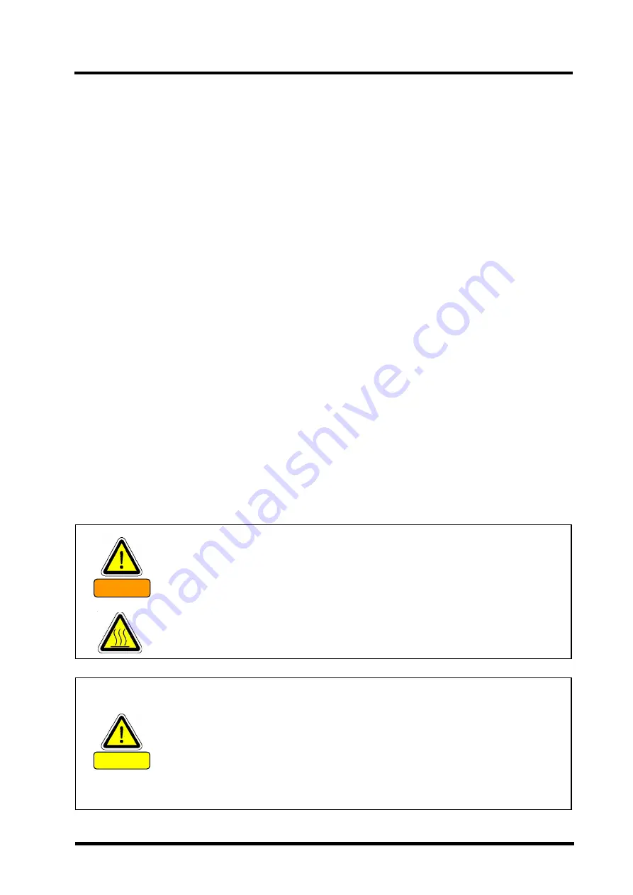
Be sure to close the Vacuum valve and stop the Pump operation to open the 
Leak valve. Failure to follow this operation might cause the oil invasion in the 
casing from the Lubrication chamber or otherwise give damage to the Pump. 
Further  the  oil  might  flow  back  to  the  Vacuum  tank  if  used  the  Oil  rotation 
pump as the Supplementary pump. 
 
If failed in closing the Vacuum valve, the vacuum might leak from the Exhaust 
system through the Pump. 
 

CAUTION


The vacuum pump becomes high temperature during operation (70

  to 80

). 

Do  not  touch  the  Motor  and/or  Pump  unit  until  the  Pump  cools  down  after 
having stopped operation.  Apply an appropriate protection to avoid to touch 
the surface as necessary. 


However, if the environment was highly humid, keep the Mechanical booster 

pump warmer than the room temperature after having stopped it and make the 
atmospheric pressure inside the Pump. Water in the air might condense in the 
Pump and worsen the ultimate pressure and/or exhaust speed.


WARNING


Summary of Contents for PRC-003A

Page 1: ...anual Mechanical Booster Pump Model PRC 003A PRC 006A PRC 012A PRC 018A Before using this product be sure to read this operation manual Keep this manual with care to use at any time ULVAC Inc Componen...

Page 2: ...be changed in the future The performance and safety of the product might not be ensured if any of the devices put together did not conform to same regulations or the product itself was modified ULVAC...

Page 3: ...er is subject to death or heavy injury WARNING If the user makes a mistake in handling it indicates a possibility that the user is subject to moderate injury or it leads to significant damage of the m...

Page 4: ...well as the Pump unit becomes toxic should the toxic gas was sucked in the vacuum pump Pay attention to execute maintenance work DANGER We would be obliged to refrain from handling and or executing m...

Page 5: ...mantling agent to wear leather gloves and use appropriate tools such as pinch bar as they have a risk of cutting the hand by nail or chip 2 Give the instruction them further to use the unloading machi...

Page 6: ...ore starting the operation WARNING Check and ensure that any of hazardous energy is blocked before starting the operation WARNING Check and ensure that any of hazardous energy is blocked before starti...

Page 7: ...njured or electrical shock by a fire or erroneous move Do not touch the Motor vacuum pump or piping during the pump operation and just after stopped it while the pump unit keeps high temperature You h...

Page 8: ...before starting install or dismantling operation WARNING Should you remove the Coolant joint immediately after having stopped the Pump there is a risk that the coolant remained inside the Pump comes t...

Page 9: ...ance or wiring be sure to turn off the primary power supply Be sure to close the lid of the terminal box before operating this unit Never open it during operation 3 During operation or for a while aft...

Page 10: ...YO99 0874 DI 002 18 ix Fig 1 Warning Label PRC 003A PRC 006A PRC 012A PRC 018A...

Page 11: ...rough transport or not 4 Whether any bolt or nut got loose or taken off through transport or not Should you found any trouble please do not hesitate to contact our Sales division or your agency IMPORT...

Page 12: ...shall be no freeze or dew formation c There shall be no dust d It shall be in house e Another pump shall not be put on the Pump f The Pump shall not be laid down nor put touching its motor edge face o...

Page 13: ...r Supply It is imperative to put the overload protective device under direction of the Electrical Installation Technical Standard 1965 Department of Trade and Industry decree No 61 Refer to 3 6 Electr...

Page 14: ...f heavy material 1 1 1 3 Warning Electric shock 2 1 1 4 Warning Explosion 2 1 1 5 Caution High temperature 3 1 1 6 Caution Leakage of hot coolant 3 1 2 Chemical Material Safety Data Sheet SDS 4 2 Pump...

Page 15: ...38 5 5 4 Pumping 38 5 5 5 Checking rotational direction 38 5 5 6 Operation 39 5 5 7 Pumping start operation 39 5 5 8 Shutdown operation 39 5 6 Optional attachment figure 40 6 Maintenance and Check 44...

Page 16: ...e 40 Fig 15 PRC 006A Optional attachment figure 41 Fig 16 PRC 012A Optional attachment figure 42 Fig 17 PRC 018A Optional attachment figure 43 Table 1 standard accessories x Table 2 Details model list...

Page 17: ...on of check or disposal Do not exhaust any hazardous gas such as toxic and combustible 1 To overhaul or dispose ask the special agency to do the detoxification process 2 Ask the disposal agency licens...

Page 18: ...the hand or bar into the opening of the Motor Motor terminal mount gets burnt Tighten close the terminal Check the tightening once a month Refer to 3 6 Electrical Connection 1 1 4 Warning Explosion F...

Page 19: ...il the temperature sufficiently cools down after having stopped the pump to conduct check or something 1 1 6 Caution Leakage of hot coolant Factors Avoidance methods and measures Kept operating withou...

Page 20: ...afety certificate in any manner CAUTION Chemical material used for this Pump 1 ULVOIL R 42 Mineral oil Standard oil for our products is either ULVOIL R 42 its combined use is not allowed The Chemical...

Page 21: ...ulting in a smooth throughput characteristic curve Especially in an application where pumping and venting are repeated the pumping speed can be shortened as compared with startup using a pressure swit...

Page 22: ...B 2290 VF80 or equivalent VG100 or equivalent Lubricating oil Genuine oil ULVOIL R 42 Mineral oil Oil requirement 0 7 1 5 1 9 1 9 Weight kg 51 86 118 150 Utilities Model PRC 003A PRC 006A PRC 012A PRC...

Page 23: ...YO99 0874 DI 002 18 7 2 3 System Flow Cooling water and power supply is required And you prepare wiring safety circuit and exhaust processing equipment etc Fig 2 Location of vacuum pump in host device...

Page 24: ...YO99 0874 DI 002 18 8 2 4 Dimensional drawing Fig 3 PRC 003A Dimensional drawing...

Page 25: ...YO99 0874 DI 002 18 9 Fig 4 PRC 006A Dimensional drawing...

Page 26: ...YO99 0874 DI 002 18 10 Fig 5 PRC 012A Dimensional drawing...

Page 27: ...YO99 0874 DI 002 18 11 Fig 6 PRC 018A Dimensional drawing...

Page 28: ...p due to moisture absorption in the pump In most cases no load run of the pump for about 24 hours will evaporate the adsorbed substance and restore the pump to normal 2 5 2 Pumping speed The pumping s...

Page 29: ...400 500 600 0 1 1 10 100 1000 10000 100000 Pumping Speed m 3 hour Pressure Pa PRC 003A 50Hz PRC 003A 60Hz PRC 006A 50Hz PRC 006A 60Hz 0 200 400 600 800 1000 1200 1400 1600 1800 2000 0 1 1 10 100 1000...

Page 30: ...the difference in intake pressure between the mechanical booster pump and the fore pump is smaller than the maximum permissible difference pressure pump having a higher performance than the standard...

Page 31: ...vacuum chamber is small in size that is when a long time can be spent for rough pumping Since the mechanical booster pump does not operate when rough pumping is under way the gas to be exhausted is d...

Page 32: ...controlled roughing valve is used which can be interlocked with a vacuum switch The vacuum switch is available in two types mechanical and electrical It is installed on the vacuum chamber or near the...

Page 33: ...not change the factory setting and starting control wiring When starting the pump by remote operation however disconnect the control wiring for the start up and turn ON OFF the mechanical no voltage c...

Page 34: ...the area such as electrical safety Cargo handling safety and so on Note that any person not attended such lectures shall be restricted from handling the product Operators shall need to attend such kin...

Page 35: ...ng PRC A Series Oil level gauge on the Cover of gear side Put the oil up to the upper limit level Oil level shall be available between level lines of 2 pieces of the oil gauge Fig 10 Oil level gauge C...

Page 36: ...vel under operation stop on the room temperature around 20 Oil level might get higher during operation due to the oil temperature rise and oil rowing but it makes no problem CAUTION To lubricate be su...

Page 37: ...s a really slight clearance to keep rotation and easily gets impossible to rotate by any foreign substance entered inside Clear the sand completely after having sand blasted the vacuum chamber Pay att...

Page 38: ...A 2 Do not connect directly the Supplementary pump inlet with the outlet of the PRC 003A PRC 006A PRC 012A PRC 018A DANGER Use of the toxic combustible or combustion susceptible gas other than inactiv...

Page 39: ...to cause break or oil leak of the casing or Oil level gauge resulting in overload of the motor CAUTION Wash sufficiently inside the Vacuum chamber pipes Vacuum valve and so on to connect them to the...

Page 40: ...ce may be for a fee Reference Standard Water Quality of Industrial Water Establishment Japan Industrial Water Association 1 Be sure to flow the Coolant with the volume indicated on Table 3 Performance...

Page 41: ...ake it possible to check the flow CAUTION 1 If you use several pumps be sure to connect the Coolant pipes parallel Cooling capacity might come down if connected them serial and cause the failure 2 You...

Page 42: ...13 8 PRC 018A 5 5 22 0 21 0 20 0 1 Rated current value of the Motor shall vary subject to its mechanism Use the Electromagnetic breaker applicable to operate by the rated current value of the applica...

Page 43: ...ARNING Install and operate the product in compliance with the laws and regulations relating to the safety e g Fire Defense Law Electric wiring regulation and so on In the country and region you use th...

Page 44: ...block it b Run the Supplementary pump to exhaust inside the Mechanical booster pump This time confirm that the pressure of the suction inlet or outlet of the booster pump comes down around the ultimat...

Page 45: ...check and ensure that it is open WARNING The Pump oil might deteriorate in a shorter time depending on the use It is recommended to replace the first Pump oil within ten days after operation start an...

Page 46: ...here the environment temperature comes down below 5 under the state that the operation is stopped Supply the compressed air of 0 3MPaG gauge pressure through the Cooling water inlet without closing th...

Page 47: ...the Motor control equipment in a short interval particularly of the atmospheric pressure operation specification might cause a trouble CAUTION Ensure to flow the Coolant with the specified volume Lac...

Page 48: ...ion products 5 4 Motor control equipment By using an Motor control equipment this pump can be operated from atmospheric pressure You can while constantly monitoring the shaft power minimum power suppl...

Page 49: ...and FR D720 Series Manufacturing after April 2009 which use it by PRC Series Please set it after confirming the model of the control equipment For the operation of the controller and electrical wirin...

Page 50: ...6 9 3 15 1 21 0 19 Base frequency voltage 200 22 Stall prevention operation level 70 0 82 5 84 5 75 0 57 Restart casting time 0 58 Restart cushion time 1 65 Retry selection 0 67 Number of retries at...

Page 51: ...ation level 70 0 83 0 85 0 75 0 P30 Enhanced function display selection 1 P53 Frequency setting operation selection 0 P57 Restart casting time 0 P58 Restart cushion time 1 P60 AU terminal slection 10...

Page 52: ...ed PU detection PU stop selection 1 P77 Parameter write selection 1 P78 Reverse rotation prevention selection 1 P79 Operation mode selection 3 P80 Motor capacity 0 75 2 2 3 7 5 5 P122 PU communication...

Page 53: ...sition of the exhaust port of rooms lubrication refer to Section 5 6 Optional attachment figure Table 10 Optional parts Description Function Oil trap flange Oil trap plug Allows pumping of the lubrica...

Page 54: ...he pump for evacuating the lubricating chamber to evacuate the lubricating chamber of the mechanical booster pump Then run the backing pump to evacuate the mechanical booster pump Here make sure that...

Page 55: ...echanical booster pump Then start the backing pump to evacuate the mechanical booster pump and piping 2 Open the main valve above the inlet side of the mechanical booster pump to evacuate the vacuum c...

Page 56: ...YO99 0874 DI 002 18 40 5 6 Optional attachment figure Fig 14 PRC 003A Optional attachment figure...

Page 57: ...YO99 0874 DI 002 18 41 Fig 15 PRC 006A Optional attachment figure...

Page 58: ...YO99 0874 DI 002 18 42 Fig 16 PRC 012A Optional attachment figure...

Page 59: ...YO99 0874 DI 002 18 43 Fig 17 PRC 018A Optional attachment figure...

Page 60: ...y every day to see the system condition 1 You should check following points at least once per three days while you continue operation 2 Whether the Vacuum oil pump oil volume is between two level line...

Page 61: ...y pressure Check cooling water piping 3 Oil color Whitish turbid Mixing of water Change oil Discolored to brown Contamination with product or acid Discolored to black Contamination with abrasion powde...

Page 62: ...rotective gear such as rubber gloves protective goggles and the like Be sure to look through the 1 2 Chemical Material Safety Data Sheet before the lubrication Should the Vacuum pump oil touched to yo...

Page 63: ...bed above Overhaul shall be required to keep the performance as well as the safety and further to continue the production on forecast Please contact the Service Center close to you listed at the end o...

Page 64: ...ly 3 Is the rotor rotation resisted Rotors do not rotate by inertia Disassemble and repair the pump Cleaning and clearance adjustment 4 Any deposits on the rotor surface No clearance due to deposits 5...

Page 65: ...stment Abnormal sound 1 Is the oil level within the level lines Oil level is below the level line Replenish oil 2 Any sound clattering synchronized with rotating speed Clattering is heard Disassemble...

Page 66: ...e with the nitrogen gas completely the Pump that exhausted any special gas Note further that only the entitled person for special gas handling should be in charge of the removal work Keep applying a p...

Page 67: ...any toxic gas Note that you are requested to bear the cost and charges relating to the disposal You should ask a special disposal agency for the disposal particularly if the Pump has exhausted any tox...

Page 68: ...andard specifications although the product is used under the service conditions described in this document such as temperature range and power etc 2 Direct export transaction Product which has damage...

Page 69: ...roduct deficiency or secondary damnification occurred to Buyer from law suit to ULVAC by third party for patent infringement 9 The reason of the failure deemed below the specified usage condition by U...

Page 70: ...sing side cover 5 O ring V100 FPM 1 Intake port 6 O ring S12 FPM 5 Communicating port 7 O ring S22 FPM 4 Rotor shaft 8 O ring P32 FPM 1 Separate exhaust port 9 O ring P18 FPM 2 Seal plug 10 O ring P9...

Page 71: ...over 5 O ring V100 FPM 1 Intake port 6 O ring S12 FPM 5 Communicating port 7 O ring S26 FPM 4 Rotor shaft 8 O ring P32 FPM 1 Separate exhaust port 9 O ring P18 FPM 2 Seal plug 10 O ring P9 FPM 1 Separ...

Page 72: ...ver 5 O ring V120 FPM 1 Intake port 6 O ring P16 FPM 6 Communicating port 7 O ring S32 FPM 4 Rotor shaft 8 O ring P32 FPM 1 Separate exhaust port 9 O ring P18 FPM 2 Seal plug 10 O ring P9 FPM 1 Separa...

Page 73: ...ver 5 O ring V175 FPM 1 Intake port 6 O ring P16 FPM 6 Communicating port 7 O ring S32 FPM 4 Rotor shaft 8 O ring P32 FPM 1 Separate exhaust port 9 O ring P18 FPM 2 Seal plug 10 O ring P9 FPM 1 Separa...

Page 74: ...products are observed The environmental protection validity date is not the product warranty period Name of parts Hazardous substances or elements Pb Hg Cd Cr6 PBB PBDE Body indicating that content o...

Page 75: ...ion Remarks Contaminant Check an applicable box I guarantee that above returned item s is not contaminated with harmful substances Above returned item s is contaminated with the following harmful subs...

Page 76: ......

Reviews: