background image

DSP 402 drive profile


©

 TR-Electronic GmbH 2007, All Rights Reserved 

Printed in the Federal Republic of Germany 

Page 144 of 260 

TR - EMO - BA - DGB - 0013 - 00 

05/16/2007 


3 DSP 402 drive profile 

 
The linguistic devices for controlling the drive are extensively independent of the 
manufacturer. For this reason, communication between the drive and the 
superimposed control system has been standardized in so-called 

drive profiles


drive profile

 specifies how an electrical drive is controlled via a field bus. It defines 

the behavior of the device and the method of accessing the drive data. The following 
sub areas in particular are controlled: 
 

  Control and status monitoring 

 Standardized 

parameterization 

  Changing operating modes 


encoTRive supports the DSP 402 profile (CiA [2002b]) as CAN node 


The following information is typically exchanged between a master (e.g. control 
system) and a drive, which assumes a "slave" function: 
 
The drive provides information on its current status (e.g. "

Drive running"

) and possibly 

additional information such as the current position, current speed etc. In the other 
direction, the control system assigns positioning orders, for example, (

"Move at speed 

x to position y"

). Without the DSP 402 profile, each manufacturer would have to 

specify its own protocols for the transmission of commands and status messages, and 
there would consequently be many applications performing the same task in different 
ways. 


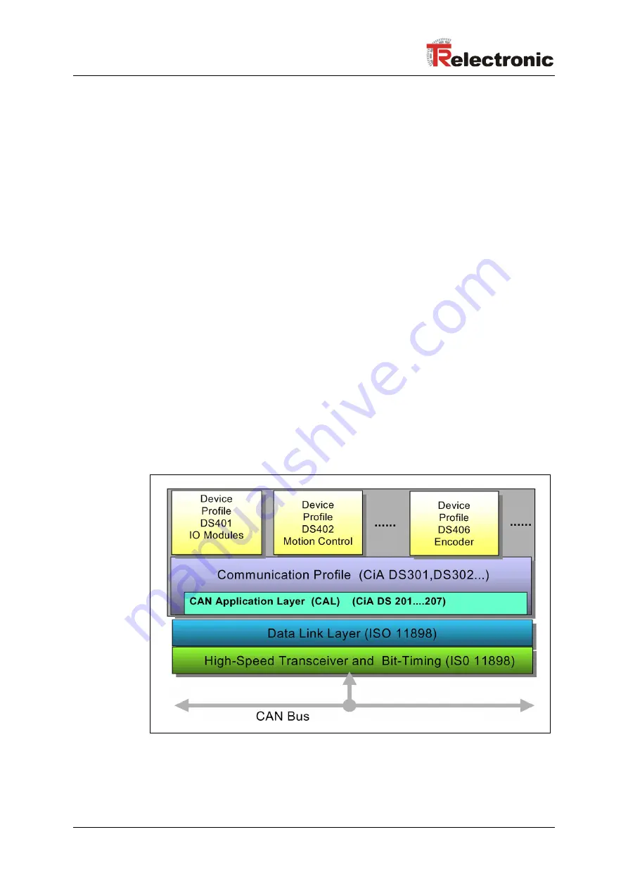
Figure 1: CANopen application profiles 


Summary of Contents for encoTRive MD-025-CO-C Series

Page 1: ...alized positioning drives MD 025 CO CXXX Series with CANopen interface Zusätzliche Sicherheitshinweise Additional safety instructions CANopen Kommunikation CANopen communication Konfiguration Parametrierung Configuration Parameterization Störungsbeseitigung Diagnose Troubleshooting Diagnosis MD 025 CO CXXX Seite 2 130 Page 131 260 D GB ...

Page 2: ...nehmigung durch den Hersteller Zuwiderhandlungen verpflichten zu Schadenersatz Änderungsvorbehalt Jegliche Änderungen die dem technischen Fortschritt dienen vorbehalten Dokumenteninformation Ausgabe Rev Datum 05 16 2007 Dokument Rev Nr TR EMO BA DGB 0013 00 Dateiname TR EMO BA DGB 0013 00 DOC Verfasser MÜJ Schreibweisen Kursive oder fette Schreibweise steht für den Titel eines Dokuments oder wird ...

Page 3: ...gt die Binärdarstellung einer Zahl an Dabei steht das Bit mit Wertigkeit 20 rechts 0001 0010 bin ist die Binärdarstellung der Dezimalzahl 18 Literatur CiA 2001 CiA Draft Standard Proposal 306 Electronic Data Sheet Specification for CANopen Version 1 1 Jun 2001 CiA 2002a CiA Draft Standard 301 CANopen Application Layer and Communication Profile Version 4 02 Feb 2002 CiA 2002b CiA Draft Standard Pro...

Page 4: ...1 1 SDO Nachrichtenformat 22 4 2 2 2 PDO Process Data Object SYNC Synchronisation 24 4 2 2 2 1 PDOs anfordern Remote Transmission Request 25 4 2 2 2 2 Parameter Objekte für PDO Konfigurierung 26 4 2 2 3 EMCY Emergency Dienst 27 4 2 2 4 Heartbeat 28 4 2 2 5 Netzwerkmanagement Dienste 28 4 2 2 5 1 NMT Dienste zur Gerätekontrolle 28 4 2 2 5 2 NMT Dienste zur Verbindungsüberwachung 30 4 2 3 Antriebssp...

Page 5: ...artbeat Producer Time 67 4 2 4 4 17 Objekt 0x1018 Identity Objekt Geräteinformationen 68 4 2 4 4 18 Objekte 0x1400 0x1405 Kommunikation Empfangs PDOs 70 4 2 4 4 19 Objekte 0x1600 0x1605 Mapping Empfangs PDOs 72 4 2 4 4 20 Objekte 0x1800 0x1805 Kommunikation Sende PDOs 74 4 2 4 4 21 Objekte 0x1A00 0x1A05 Mapping Sende PDOs 77 4 2 4 5 Herstellerspezifische Objekte 79 4 2 4 5 1 Objekt 0x2DFE Flash 79...

Page 6: ...4 2 4 6 39 Objekt 0x6084 Bremsbeschleunigung 107 4 2 4 6 40 Objekt 0x6085 Bremsbeschleunigung für Zwischenhalt 107 4 2 4 6 41 Objekt 0x6087 Drehmoment Steigung 107 4 2 4 6 42 Objekt 0x608F Auflösung des Positionsgebers 108 4 2 4 6 43 Objekt 0x6090 Auflösung des Geschwindigkeitsgebers 109 4 2 4 6 44 Objekt 0x6093 Positionsfaktor 110 4 2 4 6 45 Objekt 0x6094 Geschwindigkeitsfaktor 111 4 2 4 6 46 Obj...

Page 7: ...triebsart Positionierrampe 36 Tabelle 16 Positionierungs Parameter 39 Tabelle 17 Steuerwort Objekt 0x6040 Betriebsart Geschwindigkeitsrampe 40 Tabelle 18 Zustandswort Objekt 0x6041 Betriebsart Geschwindigkeitsrampe 41 Tabelle 19 Geschwindigkeitsrampen Parameter 43 Tabelle 20 Objektcodes bei encoTRive 54 Tabelle 21 Attribute 54 Tabelle 22 CANopen Datentypen die von encoTRive verwendet werden 54 Tab...

Page 8: ...2 Zustandsmaschine 31 Abbildung 9 Positionierrampe 37 Abbildung 10 Absolute Positionierung oben und relative Positionierung unten 38 Abbildung 11 Geschwindigkeitsrampe 42 Abbildung 12 Auszug aus einer encoTRive EDS 55 Formelverzeichnis Formel 1 Positionsgeberauflösung 44 Formel 2 Default Wert Positionsgeberauflösung 44 Formel 3 Geschwindigkeitsgeberauflösung 44 Formel 4 Default Wert Geschwindigkei...

Page 9: ...rungs Index Printed in the Federal Republic of Germany TR Electronic GmbH 2007 All Rights Reserved 05 16 2007 TR EMO BA DGB 0013 00 Page 9 of 260 Änderungs Index Änderung Datum Index Erstausgabe 16 05 07 00 ...

Page 10: ... oder kann auch separat angefordert werden 1 1 Zielgruppe Die vorliegende Dokumentation richtet sich an Inbetriebnahme Bedien und Wartungspersonal die beauftragt sind ent sprechende Tätigkeiten am Stellantrieb vorzunehmen Die entsprechende Qualifikation des Personals ist in der Montage Installationsanleitung in Kapitel Personalauswahl und qualifikation grundsätzliche Pflichten definiert 1 2 Geltun...

Page 11: ...roposal EDS Electronic Data Sheet EMCY Emergency encoTRive TR spezifischer Begriff für den Antrieb HW Hardware inc Inkremente mA Milliampere mm Millimeter mNm Millinewtonmeter mV Millivolt Nm Newtonmeter NMT Network Management OV Objektverzeichnis PC Personal Computer PDO Process Data Object PI Proportional Integral PID Proportional Integral Derivative PZD Prozessdaten ro read only RPDO Receive PD...

Page 12: ...ll Rights Reserved Printed in the Federal Republic of Germany Page 12 of 260 TR EMO BA DGB 0013 00 05 16 2007 SW Software SYNC Synchronization TPDO Transmit PDO Sende PDO V Volt wo write only ZSW Zustandswort ZSW x Bit x des Zustandsworts ...

Page 13: ...eten kann wenn die entsprechenden Vorsichtsmaßnahmen nicht getroffen werden bezeichnet wichtige Informationen bzw Merkmale und Anwen dungstipps des verwendeten Produkts 2 2 Organisatorische Maßnahmen Dieses Handbuch muss ständig am Einsatzort des encoTRives griffbereit aufbewahrt werden Das mit Tätigkeiten am encoTRive beauftragte Personal muss vor Arbeitsbeginn die Montage Installationsanleitung ...

Page 14: ...usüberwachung standardisierte Parametrierung Wechsel von Betriebsarten encoTRive unterstützt als CAN Teilnehmer das Profil DSP 402 CiA 2002b Zwischen einem Master z B Steuerung und einem Antrieb der eine Slave Funktion einnimmt werden typischerweise folgende Informationen ausgetauscht Der Antrieb teilt seinen aktuellen Zustand z B Antrieb fährt und eventuell zusätzliche Information wie die aktuell...

Page 15: ...wird der Aufbau des OV und der Zugriff auf die darin enthaltenen Objekte im Rahmen eines separaten Standards nämlich des Draft Standard 301 DS 301 CANopen Application Layer and Communication Profile CiA 2002a spezifiziert Darauf setzen anwendungsspezifische Standards wie DSP 402 oder der Standard für Encoder DS 406 auf Innerhalb eines bestimmten Profils haben bestimmte Parameter definierte Funktio...

Page 16: ...profil ist die Zustandsmaschine Hier werden die Betriebszustände und die Zustandsübergänge definiert Es wird festgelegt welche Zustände das Gerät nach dem Einschalten durchläuft und wie es in den Zustand Betriebsbereit überführt wird so dass z B eine Positionierung durchgeführt werden kann Die meisten Zustandsübergänge werden vom Master sequenziell veranlasst indem dieser im Steuerwort bestimmte B...

Page 17: ... Antriebs erforderlich sind werden über den Feldbus übertragen Abbildung 3 Antriebe am Feldbus 4 1 CANopen Kommunikationsprofil Das CANopen Kommunikationsprofil dokumentiert in CiA DS 301 regelt wie die Geräte Daten miteinander austauschen Hierbei werden Echtzeitdaten und Parameterdaten unterschieden CANopen ordnet diesen vom Charakter her völlig unterschiedlichen Datenarten jeweils passende Kommu...

Page 18: ...Reserved Printed in the Federal Republic of Germany Page 18 of 260 TR EMO BA DGB 0013 00 05 16 2007 Special Function Object SFO Synchronization SYNC Emergency EMCY Protokoll Network Management Object NMO z B Life Node Guarding Boot Up Error Control Protokoll ...

Page 19: ...an einem Identifier eine so genannte Inhibit Time zuordnen Diese definiert die Mindestpause die zwischen zwei Übertragungen einer Nachricht mit dem gleichen Identifier liegen muss Um in diesem nachrichtenbasierten System auch Teilnehmer ansprechen zu können wie es insbesondere erforderlich ist wenn bei einem Antrieb eine Positionierung gestartet werden soll wird der Identifier bei CANopen in zwei ...

Page 20: ...Service Data Objects Obwohl der CAN Bus an sich ein System von Gleichberechtigten darstellt Multi Master System gibt es bei CANopen verschiedene Rollen von denen einige typischerweise von einer Steuerung wahrgenommen werden andere typischerweise von einem Teilnehmer wie einem Antrieb Wichtige Merkmale von SDO und PDO System Parameter niederpriore Identifier Daten auf mehrere Telegramme verteilt Da...

Page 21: ...riff aus und beantwortet die Anforderung mit einer Antwort Response Im Fehlerfall gibt ein Fehlercode Auskunft über die Fehlerursache Sende SDO und Empfangs SDO werden durch ihre Funktionscodes unterschieden encoTRive stellt einen SDO Server dar und verwendet folgende Funktionscodes für SDOs Funktionscode COB ID Bedeutung 11 1011 bin 0x580 Node ID encoTRive SDO Client 12 1100 bin 0x600 Node ID SDO...

Page 22: ...equest erfolgreich war Im Falle eines Leseauftrags gibt der CCD zusätzlich Auskunft über die Anzahl der gelesenen Bytes CCD Bedeutung Gültig für 0x23 4 Byte schreiben SDO Request 0x27 3 Byte schreiben SDO Request 0x2B 2 Byte schreiben SDO Request 0x2F 1 Byte schreiben SDO Request 0x60 Schreiben erfolgreich SDO Response 0x80 Fehler SDO Response 0x40 Leseanforderung SDO Request 0x43 4 Byte Daten SDO...

Page 23: ... COB ID 0x5F0 0x580 0x70 Es handelt sich also um eine SDO Response vom Teilnehmer mit Adresse 0x70 an den SDO Client Es wurden 4 Byte Daten gelesen und der Parameterwert ist 0x0000 0001 2 670 8 40 60 60 00 00 00 00 00 5F0 8 80 60 60 00 01 00 01 06 Die erste Nachricht ist eine Leseanforderung des SDO Client an den Teilnehmer 0x70 für den Parameter 0x6060 Subindex 0 Die zweite Nachricht ist die Antw...

Page 24: ...rden und es ist möglich PDOs unter Nutzung von SDOs zu konfigurieren Bei PDOs kann der gesamte Nutzdatenbereich der CAN Nachricht 8 Byte zur Übertragung von Parameterwerten verwendet werden encoTRive unterstützt in jeder Übertragungsrichtung bis zu sechs PDOs Mit speziellen Parametern den PDO Mapping Parametern Abbildung 6 wird der Aufbau und die Inhalte die mit einer PDO transportiert werden fest...

Page 25: ...eändert hat Alternativ kann eine PDO dann gesendet werden wenn die Übertragung durch eine SYNC Nachricht angefordert wird Empfangsseitig kann ebenfalls eine synchrone Verarbeitung einer PDO konfiguriert werden Dies bedeutet dass die Daten erst verarbeitet werden wenn die nächste SYNC Nachricht empfangen wird Auf diese Weise können z B mehrere Antriebe gleichzeitig gestartet werden PDOs dürfen erst...

Page 26: ...gungsart 0x1403 Parameter für RPDO4 COB ID Übertragungsart 0x1404 Parameter für RPDO5 COB ID Übertragungsart 0x1405 Parameter für RPDO6 COB ID Übertragungsart 0x1600 Mapping für RPDO1 0x1601 Mapping für RPDO2 0x1602 Mapping für RPDO3 0x1603 Mapping für RPDO4 0x1604 Mapping für RPDO5 0x1605 Mapping für RPDO6 0x1800 Parameter für TPDO1 COB ID Übertragungsart Inhibit Time 0x1801 Parameter für TPDO2 C...

Page 27: ...Byte 1 Byte 2 Byte 3 Byte 4 Byte 5 Byte 6 Byte 7 Tabelle 6 EMCY Nachricht encoTRive verwendet das Feld Herstellerspezifische Fehlerinformation nicht Objekt Nr Beschreibung 0x1001 Fehlerregister Speichert den Wert des Felds Fehlerregister der letzten EMCY Nachricht 0x1003 Pre defined Error Field Speichert die Inhalte des Feldes Fehler Code der letzten EMCY Nachrichten Es können die letzten 8 Fehler...

Page 28: ...halb dessen eine Heartbeat Nachricht erwartet wird 0x1017 Producer Heartbeat Time Zeitintervall für das Senden einer Heartbeat Nachricht Tabelle 8 Parameter für Heartbeat 4 2 2 5 Netzwerkmanagement Dienste Das Network Management NMT hat die Aufgabe Teilnehmer eines CANopen Netzwerks zu initialisieren die Teilnehmer in das Netz aufzunehmen zu stoppen und zu überwachen NMT Dienste werden von einem N...

Page 29: ...ine aktive Verbindungsüberwachung bleibt aktiv 5 8 0x80 Enter PRE OPERATIONAL Teilnehmer soll in den Zustand PRE OPERATIONAL gehen Alle Nachrichten außer PDOs können verwendet werden 4 7 0x81 Reset Node Werte der Profilparameter des OV auf Default Werte setzen Danach Übergang in den Zustand RESET COMMUNICATION 9 10 11 0x82 Reset Communication Teilnehmer soll in den Zustand RESET COMMUNICATION gehe...

Page 30: ...eines NMT Slave anfordert Kommt innerhalb eines bestimmten Zeitintervalls keine Rückmeldung so geht der NMT Master von einem Ausfall des NMT Slave aus Ist das Life Guarding aktiv erwartet der NMT Slave innerhalb eines bestimmten Zeitintervalls eine derartige Zustandsabfrage durch den NMT Master Die NMT Dienste zur Verbindungsüberwachung verwenden den Funktionscode 1110 bin also die COB ID 0x700 No...

Page 31: ...mit gerundeten Ecken dargestellt Dabei ist jeweils die Binärdarstellung des ZSW angegeben Ein Bit welches mit x gekennzeichnet ist ist für die Zustandsermittlung nicht relevant Die Zustandsübergänge sind durch Pfeile gekennzeichnet an denen die Bedingung für den entsprechenden Übergang angegeben ist In den meisten Fällen handelt es sich dabei um ein Kommando im Steuerwort STW welches ebenfalls dur...

Page 32: ...eändert werden Eingeschaltet Switched on ZSW xxxx xxxx x01x 0011 Endstufe eingeschaltet Betriebsbereit Operation enabled ZSW xxxx xxxx x01x 0111 Der Antrieb kann gemäß der eingestellten Betriebsart verwendet werden Betriebsart Positionierrampe Zielposition kann übernommen werden Betriebsart Geschwindigkeitsrampe Antrieb beschleunigt auf die vorgegebene Zielgeschwindigkeit Zwischenhalt Quick stop a...

Page 33: ...b empfängt das Kommando Disable Operation STW xxxx xxxx 0xxx 0111 Eingeschaltet Einschaltbereit Der Antrieb empfängt das Kommando Shutdown STW xxxx xxxx 0xxx x110 Die Antriebseinheit wird deaktiviert Einschaltbereit Einschaltsperre Der Antrieb empfängt das Kommando Quick Stop STW xxxx xxxx 0xxx x01x Betriebsbereit Einschaltbereit Der Antrieb empfängt das Kommando Shutdown STW xxxx xxxx 0xxx x110 D...

Page 34: ...heit wird dann schnellstmöglich gestoppt und anschließend abgeschaltet Aus jedem Zustand Fehlerreaktion Im Antrieb ist ein Fehler aufgetreten Die entsprechende Fehlerbehandlung wird ausgeführt Fehlerreaktion Fehler Die Fehlerbehandlung ist beendet Fehler Einschaltsperre Der Fehler wurde mit einer steigenden Flanke im Bit 7 des STW quittiert Tabelle 13 Zustandsübergänge 4 2 3 2 Steuerwort und Zusta...

Page 35: ...se Bits werden zur Steuerung der Zustandsmaschine verwendet 0 Zielposition nicht übernehmen 4 Neue Zielposition 1 Zielposition übernehmen 0 Aktuelle Positionierung beenden nächste Positionierung starten 5 Parameter sofort übernehmen 1 Aktuelle Positionierung abbrechen nächste Positionierung starten 0 Zielposition ist ein Absolutwert 6 absolute relative Positionierung 1 Zielposition ist ein Relativ...

Page 36: ...0 Halt 0 Zielposition nicht erreicht Halt 1 Achse bremst ab 10 Ziel erreicht 1 Halt 0 Zielposition erreicht Halt 1 Achsengeschwindigkeit 0 11 Wert 1 Arbeitsbereich verlassen Positionswert außerhalb des vorgegebenen Bereichs Festlegung über Objekt 0x607D 0 Positionierungswerte nicht übernommen 12 Quittierung der Zielposition 1 Positionierungswerte übernommen 13 Wert 1 Schleppfehler Ein Schleppfehle...

Page 37: ... den aktuellen Einstellungen für die Geschwindigkeit Beschleunigung und Bremsbeschleunigung ergibt Abbildung 9 Positionierrampe Je nach Abstand zwischen Istposition beim Start der Positionierung und Zielposition wird die verlangte Endgeschwindigkeit 0x6081 erreicht oder nicht Bei kurzem Fahrweg folgt direkt auf die Phase mit konstanter Beschleunigung eine Phase mit konstanter Bremsbeschleunigung E...

Page 38: ...retiert d h der zurückzulegende Weg ist die Differenz aus Ist und Zielposition Bei der relativen Positionierung wird der Inhalt von Objekt 0x607A als zurückzulegender Weg interpretiert Abbildung 10 Absolute Positionierung oben und relative Positionierung unten Abbildung 10 zeigt zwei Beispiele Im oberen Teil der Abbildung wird eine absolute Positionierung auf die Zielposition 3000 durchgeführt Der...

Page 39: ...ng gestartet Ansonsten wird die aktuelle Geschwindigkeit mit der geforderten Geschwindigkeit verglichen Reicht der Verfahrweg aus wird entsprechend beschleunigt oder abgebremst 4 2 3 3 6 Abbruch einer Positionierung Wird während der Fahrt STW 8 Halt gesetzt wird die aktuelle Rampe abgebrochen und der Antrieb hält an Mit welcher Bremsbeschleunigung dies geschieht kann in Objekt 0x605D Halt Option C...

Page 40: ... integrierte Positions Mess System z B ergeben sich bei umlaufenden Anwendungen Bereichsüberschreitungen Abhängig von der Drehrichtung äußert sich dies durch einen Sprung des Positionsistwerts in Objekt 0x6064 Max Min Min Max Die Anwendung darf deshalb nicht vom Lageistwert abhängig sein 4 2 3 4 1 Steuerwort Bit STEUERWORT 0 Wert1 Betriebsbereit schalten 1 Wert1 Spannung freischalten 2 Wert1 Abbre...

Page 41: ...r 8 nicht verwendet 0 Kein Parameter Zugriff über den CAN Bus 9 Manuellbetrieb 1 Parameter Zugriff über den CAN Bus 0 Halt 0 Zielgeschwindigkeit nicht erreicht Halt 1 Achse bremst ab 10 Ziel erreicht 1 Halt 0 Zielgeschwindigkeit erreicht Halt 1 Achsengeschwindigkeit 0 11 Wert 1 Arbeitsbereich verlassen Positionswert außerhalb des vorgegebenen Bereichs Festlegung über Objekt 0x607D 0 Geschwindigkei...

Page 42: ... werden STW 1 STW 2 0x06 STW 0 0x07 STW 3 0x0F Betriebsart ausführen Antrieb dreht sich Die Rampe ergibt sich aus den aktuellen Einstellungen für die Zielgeschwindigkeit Beschleunigung und Bremsbeschleunigung Abbildung 11 Geschwindigkeitsrampe Der Antrieb beschleunigt bis zur vorgegebenen Zielgeschwindigkeit und hält die Geschwindigkeit bei bis der Antrieb manuell gestoppt wird Das Stoppen der Ach...

Page 43: ...ebs 0x6069 Gemessene Geschwindigkeit 0x6071 Ziel Drehmoment 0x6072 Maximales Drehmoment 0x607E Richtungsumkehr 0x607F Maximale Geschwindigkeit 0x6080 Maximale Motorgeschwindigkeit 0x6083 Beschleunigung begrenzt durch Objekt 0x60C5 0x6084 Bremsbeschleunigung begrenzt durch Objekt 0x60C6 0x6085 Bremsbeschleunigung für Zwischenhalt 0x6094 Geschwindigkeitsfaktor 0x606B Soll Geschwindigkeit 0x606C Ist ...

Page 44: ...des Bruchs wird in Subindex 1 festgelegt der Nenner in Subindex 2 Der Default Wert ist hungen Motorumdre nkremente Positionsi 4096 1 4096 ung eberauflös Positionsg Default Formel 2 Default Wert Positionsgeberauflösung 4 2 3 5 2 Objekt 0x6090 Auflösung des Geschwindigkeitsgebers Dieser Parameter definiert das Verhältnis zwischen Geschwindigkeitsinkrementen pro Sekunde und Motorumdrehungen pro Sekun...

Page 45: ...bjekt 0x608F definiert Der Getriebefaktor bezeichnet die Getriebeuntersetzung gegeben durch ungen llenumdreh Antriebswe hungen Motorumdre ktor Getriebefa Formel 6 Getriebefaktor Gear Ratio Der Weg pro Getriebeumdrehung ist in Positionseinheiten gegeben Der Zähler des Positionsfaktors wird als Subindex 1 von Objekt 0x6093 angegeben der Nenner als Subindex 2 Es gilt Position Positionseinheiten Posit...

Page 46: ...gung Weg pro Getriebeumdrehung Beispiel 2 Positionseinheit Inc Weg pro Getriebeumdrehung 4096 Inc Getriebefaktor 1 Positionsgeberauflösung 4096 Inc Folgende Werte sind in Objekt Positionsfaktor 0x6093 einzutragen Subindex 1 4096 Positionsgeberauflösung x Getriebefaktor Subindex 2 4096 Weg pro Getriebeumdrehung Beispiel 3 Positionseinheit Grad 10 Weg pro Getriebeumdrehung 360 Grad 3600 10 Grad Getr...

Page 47: ...n Subindex 1 von Objekt 0x6094 angegeben der Nenner als Subindex 2 Der Default Wert beträgt 30000000 2 or gkeitsfakt Geschwindi 31 Default Formel 9 Default Wert Geschwindigkeitsfaktor Dieser Wert entspricht zusammen mit der Geschwindigkeitsgeberauflösung aus Formel 4 und einer Getriebeuntersetzung von 1 1 der Geschwindigkeitseinheit U min Objekt 0x606C Actual Velocity trägt die aktuelle Abtriebsge...

Page 48: ...nheit Grad 10 sec am Abtrieb Abtriebsumdrehung 1 U sec 3600 Grad 10 1 sec Getriebefaktor 1 Default Wert für Geschwindigkeitsgeberauflösung 2 31 5000 siehe Formel 4 Folgende Werte sind in Objekt Geschwindigkeitsfaktor 0x6094 einzutragen Subindex 1 31 2 Subindex 2 18000000 1 3600 5000 Berechung 231 5000 x 1 3600 231 5000 3600 1 Beispiel 3 Geschwindigkeitseinheit mm 1000 sec am Abtrieb Weg pro Getrie...

Page 49: ...n benutzerdefinierten Beschleunigungseinheiten umgerechnet Der Zähler des Beschleunigungsfaktors wird als Subindex 1 vom Objekt 0x6097 angegeben der Nenner als Subindex 2 sec2 sec drehung Abtriebsum eiten_pro gungsseinh Beschleuni tersetzung Getriebeun rauflösung gkeitsgebe Geschwindi r gungsfakto Beschleuni Formel 10 Beschleunigungsfaktor Der Default Wert beträgt 30000000 2 r gungsfakto Beschleun...

Page 50: ...einheit Grad 10 sec2 am Abtrieb Abtriebsumdrehung 1 U sec 3600 Grad 10 1 sec2 Getriebefaktor 1 Default Wert für Geschwindigkeitsgeberauflösung 2 31 5000 siehe Formel 4 Folgende Werte sind in Objekt Geschwindigkeitsfaktor 0x6097 einzutragen Subindex 1 31 2 Subindex 2 18000000 1 3600 5000 Berechung 231 5000 x 1 3600 231 5000 3600 1 Beispiel 3 Beschleunigungseinheit mm 1000 sec2 am Abtrieb Weg pro Ge...

Page 51: ...en rauflösung gkeitsgebe Geschwindi aktor Positionsf ung eberauflös Positionsg r gungsfakto Beschleuni or onUnitFact onToPositi Accelerati rauflösung gkeitsgebe Geschwindi aktor Positionsf ung eberauflös Positionsg or gkeitsfakt Geschwindi itFactor PositionUn VelocityTo Durch Multiplikation mit dem VelocityToPositionUnitFactor wird eine benutzerdefi nierte Geschwindigkeitsangabe in Geschwindigkeit...

Page 52: ...igkeitsfaktor ergibt sich gemäß Formel 9 Die Beschleunigungsphase und die Bremsphase dauern jeweils tacc tdec 2640 150 17 60 sec VelocityToPositionUnitFactor 231 300000 216 216 360 231 5000 5000 360 300000 6 AccelerationToPositionUnitFactor 6 Die Geschwindigkeit 2640 rpm beträgt in Positionseinheiten vend 2640 6 15840 Grad sec Für die Beschleunigung und die Bremsbeschleunigung 150 rpm sec ergibt s...

Page 53: ...ente Für den Geschwindigkeitsfaktor ergibt sich Geschwindigkeitsfaktor 40 231 300000 Daraus ergibt sich VelocityToPositionUnitFactor 40 231 300000 216 40 216 231 5000 5000 300000 1 60 AccelerationToPositionUnitFactor 1 60 Die Beschleunigungsphase dauert tacc 12 sec die Bremsphase tdec 4 sec Für die Beschleunigung ergibt sich a 20 1 60 1 3 mm sec für die Bremsbeschleunigung b 60 1 60 1 mm sec Die E...

Page 54: ... den Zugriff auf diesen Parameter festlegen Attribut Bedeutung rw read write Parameter kann gelesen und geschrieben werden ro read only Parameter kann nur gelesen werden wo write only Parameter kann nur geschrieben werden const Wert ist konstant und nur lesbar Tabelle 21 Attribute encoTRive verwendet folgende Datentypen Kodierung Datentyp Länge Beschreibung 1 BOOLEAN 8 Bit Zwei mögliche Werte 0 fa...

Page 55: ...ber welche Objekte vorhanden sind und wie auf diese Objekte zugegriffen werden kann Im Lieferumfang von encoTRive ist die EDS Datei Dateiendung eds enthalten Es folgt ein Auszug aus der EDS Datei für encoTRive 6081 ParameterName Profile Velocity ObjectType 0x07 DataType 0x0007 LowLimit 1 AccessType rw DefaultValue 12000 PDOMapping 1 Unit Velocity unit Def 12000 rpm 6083 ParameterName Profile Accel...

Page 56: ...ers Attribut Angabe in der Form Zugriff Flash Speicherung Werkvoreinstellung Zugriff Zugriff auf den Parameter siehe Tabelle 21 Flash Speicherung f Parameter wird bei Anforderung Speichern im Flash im Flash gespeichert Parameter wird nicht im Flash gespeichert Werksvoreinstellung w Parameter wird bei Laden der Werksvoreinstellungen mit Default vorbelegt Wert wird nicht mit Default vorbelegt Objekt...

Page 57: ...P 402 0x192 Wert 2 im höherwertigen Wort kennzeichnet einen Servoantrieb 4 2 4 4 2 Objekt 0x1001 Fehlerregister Objektcode VAR Datentyp UNSIGNED8 Attribut ro Default 0 Min Max PDO Mapping ja Beschreibung Das Fehlerregister zeigt bitkodiert den Fehlerzustand des Geräts an Ein gesetztes Bit zeigt an dass ein entsprechender Fehler vorliegt Die genaue Fehlerursache kann Objekt 0x1003 entnommen werden ...

Page 58: ...its 0 15 kann aus der Tabelle 34 auf Seite 125 entnommen werden Subindex 0 Anzahl der Fehlereinträge Datentyp UNSIGNED8 Attribut rw Default 0 Min 0 Max 8 PDO Mapping Beschreibung Enthält die Anzahl der gespeicherten Fehler Schreiben des Werts 0 in dieses Element bedeutet dass die komplette Fehlerliste gelöscht wird Andere Werte sind nicht zulässig und führen zu einer Abort Message mit dem Fehler C...

Page 59: ...006 Min Max PDO Mapping Beschreibung Enthält die maximale Anzahl PDOs in beiden Übertragungsrichtungen Bit 0 15 Vom encoTRive gesendete PDOs 6 Bit 16 31 Vom encoTRive empfangene PDOs 6 Subindex 1 Anzahl synchrone PDOs Datentyp UNSIGNED32 Attribut ro Default 0x00060006 Min Max PDO Mapping Beschreibung Enthält die maximale Anzahl synchroner PDOs in beiden Übertragungsrichtungen Bit 0 15 Vom encoTRiv...

Page 60: ...ndet wird Bit Bedeutung 31 ohne Bedeutung 30 0 Gerät erzeugt keine SYNC Nachricht 1 Gerät erzeugt eine SYNC Nachricht 29 0 11 Bit Identifier CAN 2 0A 1 29 Bit Identifier CAN 2 0B 28 0 Identifier 29 Bit bzw 11 Bit Default Wert 0x0000 0080 encoTRive sendet keine SYNC Nachricht encoTRive verwendet den 11 Bit Identifier 0x80 für eine SYNC Nachricht 4 2 4 4 6 Objekt 0x1008 Gerätebezeichnung des Herstel...

Page 61: ...ntyp Visible String Attribut const Default V4 3 28 Feb 2006 Min Max PDO Mapping Beschreibung Das Objekt enthält die Software Version des Geräts Diese setzt sich aus einer ASCII Zeichenfolge zusammen 4 2 4 4 9 Objekt 0x100C Guard Time Objektcode VAR Datentyp UNSIGNED16 Attribut rw Default 0 Min 0 Max 65535 PDO Mapping Beschreibung Dieser Parameter legt das Zeitintervall für die Überwachung des Slav...

Page 62: ...n Life Guarding 4 2 4 4 11 Objekt 0x1010 Speichern von Parametern Objektcode ARRAY Beschreibung Mit diesem Parameter wird das remanente Speichern bestimmter Parameter veranlasst Die Auswahl der zu speichernden Parameter erfolgt über die Elemente des Parameters Subindex 0 Anzahl Einträge Datentyp UNSIGNED8 Attribut ro Default 4 Min Max PDO Mapping Beschreibung Enthält den größten Array Subindex Sub...

Page 63: ...dex 3 Anwendungsparameter speichern Datentyp UNSIGNED32 Attribut rw Default 0 Min Max PDO Mapping Beschreibung Alle speicherbaren Antriebs Profilparameter Bereich 0x6000 0x9FFF speichern Das Speichern erfolgt nur dann wenn der Wert 0x65766173 geschrieben wird Dies ist der Zahlenwert den die Zeichenkette save s 0x73 a 0x61 v 0x76 e 0x65 ergibt Subindex 4 Herstellerspezifische Parameter speichern Da...

Page 64: ...tentyp UNSIGNED32 Attribut rw Default 0 Min Max PDO Mapping Beschreibung Alle Parameter für die Werksvoreinstellungen vorliegen mit Werksvoreinstellungen belegen Dies geschieht nur dann wenn der Wert 0x64616F6C geschrieben wird Dies ist der Zahlenwert den die Zeichenkette load l 0x6C o 0x6F a 0x61 d 0x64 ergibt Subindex 2 Werksvoreinstellungen für Kommunikationsparameter Datentyp UNSIGNED32 Attrib...

Page 65: ... a 0x61 d 0x64 ergibt Subindex 4 Werksvoreinstellungen für herstellerspezifische Parameter Datentyp UNSIGNED32 Attribut rw Default 0 Min Max PDO Mapping Beschreibung Alle Parameter aus dem Bereich 0x2000 0x5FFF für die Werksvoreinstellungen vorliegen mit Werksvoreinstellungen belegen Dies geschieht nur dann wenn der Wert 0x64616F6C geschrieben wird Dies ist der Zahlenwert den die Zeichenkette load...

Page 66: ...eat Time Objektcode ARRAY Beschreibung Mit diesem Parameter wird das Zeitintervall festgelegt innerhalb dessen eine Heartbeat Nachricht erwartet wird Es werden maximal zwei Teilnehmer als Heartbeat Producer unterstützt Subindex 0 Anzahl Einträge Datentyp UNSIGNED8 Attribut ro Default 2 Min Max PDO Mapping Beschreibung Enthält den größten Array Subindex Subindex 1 Consumer Heartbeat Time 1 Datentyp...

Page 67: ...itintervall in ms fest innerhalb dessen eine Heartbeat Nachricht vom Teilnehmer dessen Node ID in den Bits 23 16 abgelegt ist erwartet wird Eine Heartbeat Zeit von 0x00 bedeutet dass keine Heartbeat Nachricht erwartet wird 4 2 4 4 16 Objekt 0x1017 Heartbeat Producer Time Objektcode VAR Datentyp UNSIGNED16 Attribut rw Default 0 Min 0 Max 65535 PDO Mapping Beschreibung Dieser Parameter legt das Zeit...

Page 68: ...dex Subindex 1 Herstelleridentifikation Datentyp UNSIGNED32 Attribut ro Default 0 Min Max PDO Mapping Beschreibung Eindeutige Identifikation des Herstellers Subindex 2 Product Code Datentyp UNSIGNED32 Attribut ro Default 736025 Min Max PDO Mapping Beschreibung Identifiziert die Geräteversion Subindex 3 Revisionsnummer Datentyp UNSIGNED32 Attribut ro Default 0x00040003 Min Max PDO Mapping Beschreib...

Page 69: ...deral Republic of Germany TR Electronic GmbH 2007 All Rights Reserved 05 16 2007 TR EMO BA DGB 0013 00 Page 69 of 260 Subindex 4 Seriennummer Datentyp UNSIGNED32 Attribut ro Default 1 Min Max PDO Mapping Beschreibung Seriennummer des Geräts ...

Page 70: ...r RPDO4 Objekt 0x1404 Kommunikationsparameter für RPDO5 Objekt 0x1405 Kommunikationsparameter für RPDO6 Objektcode RECORD Beschreibung Jeder dieser Parameter konfiguriert eine Empfangs PDO Subindex 0 Anzahl Einträge Datentyp UNSIGNED8 Attribut ro Default 2 Min Max PDO Mapping Beschreibung Enthält den größten Array Subindex Subindex 1 COB ID Datentyp UNSIGNED32 Attribut rw Default Index 0x1400 Node...

Page 71: ...0 Subindex 2 Übertragungsart Datentyp UNSIGNED8 Attribut rw Default 255 Min 0 Max 255 PDO Mapping Beschreibung Legt fest wie empfangene PDO Daten vom encoTRive zu verarbeiten sind Tabelle 23 Übertragungsart RPDO Wert Bedeutung 0 240 Synchron RPDO wird sofort nach Empfang der nächsten SYNC Nachricht ausgewertet 255 RPDO wird sofort nach Empfang ausgewertet ...

Page 72: ... 8 PDO Mapping Beschreibung Tatsächliche Anzahl der in gemappten Objekte Wert 0 bedeutet RPDO deaktiviert Wenn Mapping Einträge hinzugefügt werden müssen sind zuerst die neuen Einträge anzulegen Erst danach darf die Anzahl der Elemente geändert werden Subindex 1 Erstes gemapptes Objekt Datentyp UNSIGNED32 Attribut rw Default Objekt 0x1600 0x0000 0000 Objekt 0x1601 0x0000 0000 Objekt 0x1602 0x0000 ...

Page 73: ...en tieren die ersten beiden Bytes Länge 0x20 32 Bits Byte 3 und 4 Subindex 0x00 und Byte 5 bis 8 Index 0x6081 Geschwindigkeit Beispiel RPDO Mapping Mit einer PDO Nachricht können bis zu 8 Byte Daten aus Bereichen des Objektverzeichnisses die ein PDO Mapping unterstützen übertragen werden Byte 0 Byte 1 Byte 2 Byte 3 Byte 4 Byte 5 Byte 6 Byte 7 RPDO1 Maximalstrom 0x6073 16 Bit Soll Betriebsart 0x606...

Page 74: ... Objekt 0x1804 Kommunikationsparameter für TPDO5 Objekt 0x1805 Kommunikationsparameter für TPDO6 Objektcode RECORD Beschreibung Jeder dieser Parameter konfiguriert eine TPDO Subindex 0 Anzahl Einträge Datentyp UNSIGNED8 Attribut ro Default 5 Min Max PDO Mapping Beschreibung Enthält den größten Array Subindex Subindex 1 COB ID Datentyp UNSIGNED32 Attribut rw Default Objekt 0x1800 Node ID 0x180 Obje...

Page 75: ... wird nur dann gesendet wenn sie durch eine entsprechende Remote Transmission Request angefordert wird Die Sendedaten werden mit Empfang der SYNC Nachricht aktualisiert 253 RTR gebunden Die TPDO wird nur dann gesendet wenn sie durch eine entsprechende Remote Transmission Request angefordert wird Die Sendedaten werden mit Empfang der Remote Transmission Request aktualisiert 254 Asynchron Das Senden...

Page 76: ... Subindex 5 Event Timer Datentyp UNSIGNED16 Attribut rw Default 0 Min 0 Max 65535 PDO Mapping Beschreibung Definiert ein Zeitintervall in 0 1 ms Schritten dessen Ablauf als auslösendes Ereignis für das Senden der PDO angesehen wird Dieses Ereignis wirkt zusätzlich zu anderen Ereignissen die das Senden auslösen Parameterwert 0 deaktiviert diesen Mechanismus ...

Page 77: ...Max 8 PDO Mapping Beschreibung Tatsächliche Anzahl der in gemappten Objekte Wert 0 bedeutet TPDO deaktiviert Wenn Mapping Einträge hinzugefügt werden müssen so sind diese zuerst anzulegen Erst danach darf die Anzahl der Elemente geändert werden Subindex 1 Erstes gemapptes Objekt Datentyp UNSIGNED32 Attribut rw Default Objekt 0x1A00 0x0000 0000 Objekt 0x1A01 0x0000 0000 Objekt 0x1A02 0x0000 0000 Ob...

Page 78: ...des TPDO1 im obigen Beispiel repräsentieren die ersten beiden Bytes Länge 0x20 32 Bits Byte 3 und 4 Subindex 0x00 und Byte 5 bis 8 Index 0x6064 Lageistwert Beispiel TPDO Mapping Mit einer PDO Nachricht können bis zu 8 Byte Daten aus Bereichen des Objektverzeichnisses die ein PDO Mapping unterstützen übertragen werden Byte 0 Byte 1 Byte 2 Byte 3 Byte 4 Byte 5 Byte 6 Byte 7 TPDO1 Statuswort 0x6041 1...

Page 79: ...ed 05 16 2007 TR EMO BA DGB 0013 00 Page 79 of 260 4 2 4 5 Herstellerspezifische Objekte 4 2 4 5 1 Objekt 0x2DFE Flash Objektcode VAR Datentyp DOMAIN Attribut rw Default Min Max PDO Mapping Beschreibung Unterstützt das Laden neuer Firmware Stände Lesen Firmware Verifizierung Schreiben Firmware Update laden ...

Page 80: ... Ergebnis Datentyp UNSIGNED16 Attribut ro Default 0 Min Max PDO Mapping ja Beschreibung Fehlercode bei Ausführen des Selbsttests nach Stromversorgung EIN Wenn kein Fehler aufgetreten ist ist das Ergebnis 0 Andernfalls wird eine EMCY Nachricht abgesetzt siehe Kapitel 6 2 EMCY Fehlerinformation ab Seite 123 und der Antrieb wird abgeschaltet Statuswort Nicht betriebsbereit Subindex 2 Temperatursensor...

Page 81: ... ro Default 0 Min Max PDO Mapping ja Beschreibung Beinhaltet den Istwert der HEX Schalter für die Baudrate und Knoten Adresse Byte n Knoten Adresse Byte n 1 Baudrate Subindex 6 Ist Drehmoment erzeugende Strom Begrenzung Datentyp UNSIGNED16 Attribut ro Default 0 Min Max PDO Mapping ja Beschreibung Einheit Motor Nennstrom 1000 Die Wurzel der Quadratsumme aus Objekt 6073 Maximalstrom und Objekt 2F02 ...

Page 82: ...nberechnung in PWM Zyklen Datentyp UNSIGNED16 Attribut ro Default 0 Min Max PDO Mapping ja Beschreibung 4 2 4 5 3 Objekt 0x2E04 Kalibrierungsschlüssel Objektcode RECORD Beschreibung Schreibschutz für die automatische Kalibrierung des Antriebs Wird nur vom Hersteller benötigt Subindex 0 Anzahl Einträge Datentyp UNSIGNED8 Attribut ro Default 7 Min Max PDO Mapping Beschreibung Anzahl der folgenden Ei...

Page 83: ...x 1 Warnungstemperatur Datentyp UNSIGNED16 Attribut rw Default 75 Min Max PDO Mapping ja Beschreibung Der Eintrag legt die Temperatur in C fest Eine Überschreitung eines Temperatursensors führt zu einer entsprechenden EMCY Nachricht siehe Kapitel 6 2 EMCY Fehlerinformation ab Seite 123 Subindex 2 Abschalttemperatur Datentyp UNSIGNED16 Attribut rw Default 90 Min Max PDO Mapping ja Beschreibung Der ...

Page 84: ...ult 0 Min Max PDO Mapping ja Beschreibung Einheit Motor Nennstrom 1000 Um hohe Geschwindigkeiten oder niedrige DC Busspannungen zu erlauben kann der Antrieb durch erzeugen eines Blindstroms das Rotorfeld in den Statorwicklungen aufheben Dies ist die Grenze für den Blindstrom in 1 1000 des Nennstromes 0 deaktiviert die Rotorfeldaufhebung Diese Aufhebung ist keine Schwächung des Feldes und verminder...

Page 85: ...2 1 PDO Mapping Ja Beschreibung Die Busspannung ist die Versorgungsspannung für die Leistungsendstufen Die gesamte Vorwärts oder offene Regelkreisverstärkung des Stromes oder die Drehmomentregelung ist zu dieser Spannung proportional Um eine konstante Ansprechzeit für den geschlossenen Regelkreis zu erhalten nimmt die Verstärkung des PI Reglers mit der Reduzierung der Busspannung zu Wenn die Bussp...

Page 86: ...entyp UNSIGNED32 Attribut rw Default 50000 Min 0 Max 232 1 PDO Mapping Ja Beschreibung Wenn die Versorgungsspannung der Leistungsendstufen diesen Wert übersteigt werden die Lastwiderstände eingeschaltet Ihr Zweck ist es die während des Bremsens erzeugte überflüssige elektrische Energie zu vernichten Andernfalls würden sich die Buskondensatoren so hoch aufladen bis die Überspannung die Bauelemente ...

Page 87: ...itzen auf den Versorgungsleitungen Subindex 7 Stator Induktivität µH Datentyp UNSIGNED32 Attribut rw Default 200 Min 0 Max 232 1 PDO Mapping Ja Beschreibung Die proportionalen Verstärkungen des PI Stromreglers werden entsprechend nach der Statorinduktivität geteilt durch die DC Spannung eingestellt um die erforderliche Abschaltfrequenz des geschlossenen Regelkreises aufrecht zu erhalten Je nach de...

Page 88: ...gig von Thetai Massenträgheit des Rotors und die Last in kgm MN Nennmotordrehmoment in Nm oder kgm 2 s 2 iN Nennmotorstrom in mA Sinus Spitze iM aktueller Stator Strommessbereich in mA Tc 1 fc Zykluszeit des Stromreglers in Sekunden Rechenbeispiel für einen bürstenlosen 300W DC Motor ohne Last Thetai 510 10 7 kgm MN 0 63 Nm iN effektiv 7600 mA iN Spitze 2 0 5 7600 mA 10748 mA iM 24229 mA Tc 1 1000...

Page 89: ...mpendauer 1 fc Datentyp UNSIGNED32 Attribut rw Default 36000000 Min 0 Max 4294800000 PDO Mapping Ja Beschreibung fc ist die Taktfrequenz der Stromregelung Rampenpositionierungen die länger als dieser Wert andauern werden sofort abgebrochen Es wird ein Fehler gemeldet und die Emergency 6343 ausgelöst Der Vorgabewert ist 36000000 bzw 1 Stunde Der Maximalwert beträgt 119 3 Stunden ...

Page 90: ...efiniert 0 Keine Aktion 1 Übergang in Zustand Störung 2 Führe Kommando Disable Voltage aus siehe Tabelle 13 Seite 34 3 Führe Kommando Quick Stop aus siehe Tabelle 13 Seite 34 4 2 4 6 2 Objekt 0x603F Error Code Objektcode VAR Datentyp UNSIGNED16 Attribut ro Default 0 Min 0 Max 65535 PDO Mapping ja Beschreibung Dieser Parameter speichert den zuletzt aufgetretenen Fehler und entspricht den niederwert...

Page 91: ...ord Objektcode VAR Datentyp UNSIGNED16 Attribut ro Default 0 Min 0 Max 65535 PDO Mapping ja Beschreibung In diesem Objekt überträgt der Antrieb Zustandsinformationen siehe Abschnitte 4 2 3 2 4 2 3 3 2 und 4 2 3 4 2 4 2 4 6 5 Objekt 0x604D Pol Paar Zahl Objektcode VAR Datentyp UNSIGNED8 Attribut ro Default 1 Min 2 Max PDO Mapping ja Beschreibung Enthält die Anzahl der Polpaare des verwendeten Motor...

Page 92: ...tützt Tabelle 25 Werte für Quick Stop Option Code Wert Bedeutung 0 Antrieb abschalten Nach Erreichen des Stillstands geht der Antrieb in den Zustand Einschaltsperre 1 Antrieb mit aktueller Bremsbeschleunigung in den Stillstand abbremsen Danach geht der Antrieb in den Zustand Einschaltsperre 2 Antrieb mit Bremsbeschleunigung für Zwischenhalt 0x6085 abbremsen Nach Erreichen des Stillstands geht der ...

Page 93: ...6 Werte für Shutdown Option Code Wert Bedeutung 0 Antrieb abschalten 1 Antrieb mit aktueller Bremsbeschleunigung in den Stillstand abbremsen Danach Antrieb abschalten 4 2 4 6 8 Objekt 0x605C Verhalten bei Disable Operation Disable Operation Option Code Objektcode VAR Datentyp INTEGER16 Attribut rw Default 1 Min 32768 Max 32767 PDO Mapping Beschreibung Mit diesem Parameter kann die Reaktion des Ant...

Page 94: ...767 PDO Mapping Beschreibung Mit diesem Parameter kann die Reaktion des Antriebs festgelegt werden wenn Bit 8 Motor stoppen im Steuerwort aktiv ist Folgende Werte werden vom encoTRive unterstützt Tabelle 28 Werte für Halt Option Code Wert Bedeutung 0 Antrieb abschalten 1 Antrieb mit aktueller Bremsbeschleunigung in den Stillstand abbremsen 2 Antrieb mit Bremsbeschleunigung für Zwischenhalt 0x6085 ...

Page 95: ...Tabelle 29 Werte für Fault Reaction Option Code Wert Bedeutung 0 Antrieb abschalten 1 Antrieb mit aktueller Bremsbeschleunigung in den Stillstand abbremsen 2 Antrieb mit Bremsbeschleunigung für Zwischenhalt 0x6085 abbremsen 3 Antrieb an der Stromgrenze abbremsen 4 Antrieb an der Spannungsgrenze abbremsen 4 2 4 6 11 Objekt 0x6060 Betriebsart Objektcode VAR Datentyp INTEGER8 Attribut wo Default 0 Mi...

Page 96: ...triebsart siehe Tabelle 30 Seite 95 angezeigt 4 2 4 6 13 Objekt 0x6062 Soll Position Objektcode VAR Datentyp INTEGER32 Attribut ro Default 0 Min Max PDO Mapping ja Beschreibung Dieses Objekt in Positionseinheiten enthält die anzusteuernde Position die sich aus dem Regleralgorithmus ergibt 4 2 4 6 14 Objekt 0x6064 Ist Position Objektcode VAR Datentyp INTEGER32 Attribut rw Default 0 Min Max PDO Mapp...

Page 97: ...t ist die anzusteuernde Geschwindigkeit unerreichbar ist die Reglerparameter ungünstig eingestellt sind zu hohe Beschleunigung 4 2 4 6 16 Objekt 0x6066 Schleppfehler Timeout Objektcode VAR Datentyp UNSIGNED16 Attribut rw Default 100 Min 0 Max 216 1 PDO Mapping ja Beschreibung Der Parameterwert gibt in 1 ms Schritten die Zeit an für die mindestens ein Schleppfehler vorliegen muss ehe er im Statuswo...

Page 98: ...t im Positionsfenster liegen muss ehe im Statuswort Ziel erreicht signalisiert wird 4 2 4 6 19 Objekt 0x6069 Gemessene Geschwindigkeit Objektcode VAR Datentyp INTEGER32 Attribut ro Default Min Max PDO Mapping ja Beschreibung Der Parameter enthält den am Geschwindigkeits Encoder gemessenen Geschwindigkeitswert in Geschwindigkeitsinkrementen 4 2 4 6 20 Objekt 0x606B Soll Geschwindigkeit Objektcode V...

Page 99: ...seinheiten 4 2 4 6 22 Objekt 0x6071 Ziel Drehmoment Objektcode VAR Datentyp INTEGER16 Attribut rw Default 0 Min 0 Max 10000 PDO Mapping ja Beschreibung Dieser Parameter enthält das Ziel Drehmoment Einheit Tausendstel des Nenndrehmoments 0x6076 4 2 4 6 23 Objekt 0x6072 Maximales Drehmoment Objektcode VAR Datentyp UNSIGNED16 Attribut rw Default 1250 Min 0 Max 10000 PDO Mapping ja Beschreibung Dieses...

Page 100: ...mal zulässigen Motorstrom Einheit Tausendstel des Nennstroms 0x6075 4 2 4 6 25 Objekt 0x6074 Soll Drehmoment Objektcode VAR Datentyp INTEGER16 Attribut ro Default 0 Min Max PDO Mapping ja Beschreibung Dieses Objekt enthält das Drehmoment welches sich als Ausgangsgröße der Drehmomentbegrenzung ergibt Einheit Tausendstel des Nenndrehmoments 0x6076 4 2 4 6 26 Objekt 0x6075 Motor Nennstrom Objektcode ...

Page 101: ...jekt enthält das Nenndrehmoment des Motors in mNm 4 2 4 6 28 Objekt 0x6077 Drehmoment Istwert Objektcode VAR Datentyp INTEGER16 Attribut ro Default 0 Min Max PDO Mapping ja Beschreibung Dieses Objekt enthält das aktuelle Drehmoment des Motors Einheit Tausendstel des Nenndrehmoments 0x6076 4 2 4 6 29 Objekt 0x6078 Strom Istwert Objektcode VAR Datentyp INTEGER16 Attribut ro Default 0 Min Max PDO Map...

Page 102: ...ro Default 0 Min Max PDO Mapping ja Beschreibung Dieses Objekt enthält die aktuelle Spannung des Gleichspannungszwischenkreises in mV 4 2 4 6 31 Objekt 0x607A Zielposition Objektcode VAR Datentyp INTEGER32 Attribut rww Default 0 Min 231 Max 231 1 PDO Mapping ja Beschreibung Dieses Objekt enthält die Zielposition in Positionseinheiten siehe Kapitel 4 2 3 5 Einheiten Seite 44 Je nach Bit absolut rel...

Page 103: ...ionswert automatisch an das gegenüber liegende Ende des Bereichs Dieses Verhalten kann mit dem Parameter 0x607D verhindert werden Subindex 0 Anzahl Einträge Datentyp UNSIGNED8 Attribut ro Default 2 Min Max PDO Mapping Beschreibung Gibt die Anzahl der folgenden Einträge an Subindex 1 Untere Positionsgrenze Datentyp INTEGER32 Attribut rw Default 0 Min 231 Max 231 1 PDO Mapping ja Beschreibung Minima...

Page 104: ...chinennullpunkt angegeben Bei einer neuen Zielposition wird überprüft ob sich diese im Software Positionsbereich befindet Subindex 0 Anzahl Einträge Datentyp UNSIGNED8 Attribut ro Default 2 Min Max PDO Mapping Beschreibung Gibt die Anzahl der folgenden Einträge an Subindex 1 Untere Positionsgrenze Datentyp INTEGER32 Attribut rw Default 231 Min 231 Max 231 1 PDO Mapping ja Beschreibung Minimaler Po...

Page 105: ...gkeits Istwert und Soll Geschwindigkeit mit 1 multipliziert Der Parameterwert wird wie folgt interpretiert Tabelle 31 Richtungsumkehr Bit 7 Bit 6 Bit 5 0 1 Richtungsumkehr bei Position 0 keine Richtungsumkehr bei Position 1 Richtungsumkehr bei Geschwindigkeit 0 keine Richtungsumkehr bei Geschwindigkeit reserviert 4 2 4 6 35 Objekt 0x607F Maximalgeschwindigkeit Objektcode VAR Datentyp UNSIGNED32 At...

Page 106: ... Geschwindigkeit Objektcode VAR Datentyp UNSIGNED32 Attribut rw Default 4400 Min 1 Max 232 1 PDO Mapping ja Beschreibung Dieser Parameter gibt in Geschwindigkeitseinheiten die Geschwindigkeit an die am Ende einer Beschleunigungsrampe erreicht werden soll siehe Kapitel 4 2 3 3 Betriebsart Positionierrampe Seite 35 4 2 4 6 38 Objekt 0x6083 Beschleunigung Objektcode VAR Datentyp UNSIGNED32 Attribut r...

Page 107: ...itel 4 2 3 3 Betriebsart Positionierrampe Seite 35 4 2 4 6 40 Objekt 0x6085 Bremsbeschleunigung für Zwischenhalt Objektcode VAR Datentyp UNSIGNED32 Attribut rw Default 9000 Min 1 Max 232 1 PDO Mapping ja Beschreibung Dieser Parameter gibt in Beschleunigungseinheiten die Bremsbeschleunigung an mit der bei einem Zwischenhalt abgebremst wird wenn der Quick Stop Option Code den Wert 2 hat 4 2 4 6 41 O...

Page 108: ...tnis von Positionsinkrementen zu Motorumdrehungen siehe Kapitel 4 2 3 5 Einheiten Seite 44 Subindex 0 Anzahl Einträge Datentyp UNSIGNED8 Attribut ro Default 2 Min Max PDO Mapping Beschreibung Gibt die Anzahl der folgenden Einträge an Subindex 1 Positionsinkremente Datentyp UNSIGNED32 Attribut ro Default 4096 Min Max PDO Mapping Beschreibung Positionsinkremente Subindex 2 Motorumdrehungen Datentyp ...

Page 109: ... Sekunde zu Motorumdrehungen pro Sekunde siehe Kapitel 4 2 3 5 Einheiten Seite 44 Subindex 0 Anzahl Einträge Datentyp UNSIGNED8 Attribut ro Default 2 Min Max PDO Mapping Beschreibung Gibt die Anzahl der folgenden Einträge an Subindex 1 Geschwindigkeitsinkremente Datentyp UNSIGNED32 Attribut ro Default 231 Min 1 Max 232 1 PDO Mapping Beschreibung Geschwindigkeitsinkremente pro Sekunde Subindex 2 Mo...

Page 110: ...abei werden gegebenenfalls Getriebe und Vorschub berücksichtigt siehe Kapitel 4 2 3 5 Einheiten Seite 44 Der Positionsfaktor ist das Verhältnis zwischen Positionsinkrementen und Positionseinheiten definiert über Formel 5 Subindex 0 Anzahl Einträge Datentyp UNSIGNED8 Attribut ro Default 2 Min Max PDO Mapping Beschreibung Gibt die Anzahl der folgenden Einträge an Subindex 1 Positionsinkremente Zähle...

Page 111: ...etriebe und Vorschub berücksichtigt siehe Kapitel 4 2 3 5 Einheiten Seite 44 Der Geschwindigkeitsfaktor ist das Verhältnis zwischen Geschwindigkeitsinkrementen pro Sekunde und Geschwindigkeitseinheiten definiert über Formel 8 Geschwindigkeitsfaktor Subindex 0 Anzahl Einträge Datentyp UNSIGNED8 Attribut ro Default 2 Min Max PDO Mapping Beschreibung Gibt die Anzahl der folgenden Einträge an Subindex...

Page 112: ...en gegebenenfalls Getriebe und Vorschub berücksichtigt siehe Kapitel 4 2 3 5 Einheiten Seite 44 Der Beschleunigungsfaktor ist das Verhältnis zwischen Geschwindigkeitsinkrementen pro Sekunde und Beschleunigungseinheiten definiert über Formel 10 Subindex 0 Anzahl Einträge Datentyp UNSIGNED8 Attribut ro Default 2 Min Max PDO Mapping Beschreibung Gibt die Anzahl der folgenden Einträge an Subindex 1 Be...

Page 113: ...8 Objekt 0x60C6 Maximale Bremsbeschleunigung Objektcode VAR Datentyp UNSIGNED32 Attribut rw Default 15000 Min 1 Max 232 1 PDO Mapping ja Beschreibung Dieser Parameter gibt die maximal zulässige Bremsbeschleunigung in benutzerdefinierten Beschleunigungseinheiten an 4 2 4 6 49 Objekt 0x60FD Digitale Eingänge Objektcode VAR Datentyp UNSIGNED32 Attribut ro Default 0 Min Max PDO Mapping ja Beschreibung...

Page 114: ...en Ausgänge Subindex 0 Anzahl Einträge Datentyp UNSIGNED8 Attribut ro Default 2 Min Max PDO Mapping Beschreibung Gibt die Anzahl der folgenden Einträge an Subindex 1 Ausgangsbits Datentyp UNSIGNED32 Attribut rw Default 0x0000 0000 Min Max PDO Mapping ja Beschreibung Dieses Element enthält die definierten Ausgangsbits Bit 0 0 Haltebremse geschlossen Subindex 2 Bitmaske Datentyp UNSIGNED32 Attribut ...

Page 115: ... auf die maximale Geschwindigkeit definiert über das Objekt 0x607F 4 2 4 6 52 Objekt 0x6402 Motorart Objektcode VAR Datentyp UNSIGNED16 Attribut ro Default 3 Min Max PDO Mapping Beschreibung Dieser Parameter gibt die Art des verwendeten Motors an Bei encoTRive ist dies ein Synchronmotor mit Permanentmagnet Wert 3 4 2 4 6 53 Objekt 0x6502 Unterstützte Betriebsarten Objektcode VAR Datentyp UNSIGNED3...

Page 116: ... Objekt 0x6093 SUB2 Positionsbereichvorgabe 0 für die untere Positionsgrenze Objekt 0x607B SUB1 Positionsbereichvorgabe 1 073 741 823 für die obere Positionsgrenze Objekt 0x607B SUB2 Software Positionsbereichvorgabe 1 für die untere Positionsgrenze Objekt 0x607D SUB1 Software Positionsbereichvorgabe 1 073 741 822 für die obere Positionsgrenze Objekt 0x607D SUB2 Geschwindigkeitsvorgabe 4 350 Objekt...

Page 117: ...Nicht betriebsbereit xxxx xxxx x1xx 0000 bin COB ID CCD Index SUB Daten 11 Bit Byte 0 Byte 1 Byte 2 Byte 3 Byte 4 Byte 5 Byte 6 Byte 7 Tx_SDO 0x670 0x40 0x41 0x60 0x00 0x00 0x00 0x00 0x00 Rx_SDO 0x5F0 0x4B 0x41 0x60 0x00 0x40 0x00 0x00 0x00 Knoten starten Mit dem Kommando START REMOTE NODE CCD 0x01 wird der Antrieb mit der Knotenadresse 0x70 in den NMT Zustand OPERATIONAL versetzt Als Antwort meld...

Page 118: ...e 6 Byte 7 Tx_SDO 0x670 0x23 0x7B 0x60 0x01 0x00 0x00 0x00 0x00 Rx_SDO 0x5F0 0x60 0x7B 0x60 0x01 0x00 0x00 0x00 0x00 Tx_SDO 0x670 0x23 0x7B 0x60 0x02 0xFF 0xFF 0xFF 0x3F Rx_SDO 0x5F0 0x60 0x7B 0x60 0x02 0x00 0x00 0x00 0x00 Software Positionsbereiche festlegen Der Software Positionswert für die untere Positionsgrenze 1 und die obere Positionsgrenze 0x3FFF FFFE wird über die Subindizes 1 und 2 im Ob...

Page 119: ...yte 6 Byte 7 Tx_SDO 0x670 0x23 0x84 0x60 0x00 0xE0 0x2E 0x00 0x00 Rx_SDO 0x5F0 0x60 0x84 0x60 0x00 0x00 0x00 0x00 0x00 Motorendstufe einschaltbereit schalten Die Motorendstufe des Antriebs kann jetzt über die Bits 1 und 2 im Steuerwort 0x6040 in den Zustand Endstufe einschaltbereit versetzt werden xxxx xxxx xxxx x110 bin COB ID CCD Index SUB Daten 11 Bit Byte 0 Byte 1 Byte 2 Byte 3 Byte 4 Byte 5 B...

Page 120: ...bin COB ID CCD Index SUB Daten 11 Bit Byte 0 Byte 1 Byte 2 Byte 3 Byte 4 Byte 5 Byte 6 Byte 7 Tx_SDO 0x670 0x40 0x41 0x60 0x00 0x00 0x00 0x00 0x00 Rx_SDO 0x5F0 0x4B 0x41 0x60 0x00 0x23 0x00 0x00 0x00 Betriebsart ausführen Um in der Zustandsmaschine den nächsten Status zu erreichen muss die eingestellte Betriebsart ausgeführt werden Gegenüber dem vorherigen Bitmuster muss im Steuerwort 0x6040 zusät...

Page 121: ...xxx1 1111 bin COB ID CCD Index SUB Daten 11 Bit Byte 0 Byte 1 Byte 2 Byte 3 Byte 4 Byte 5 Byte 6 Byte 7 Tx_SDO 0x670 0x2B 0x40 0x60 0x00 0x1F 0x00 0x00 0x00 Rx_SDO 0x5F0 0x60 0x40 0x60 0x00 0x00 0x00 0x00 0x00 Über das Statuswort 0x6041 Bit 12 meldet der Antrieb Zielposition wird quittiert xxx1 xxxx x011 0111 bin Dies bedeutet dass der Antrieb das Ziel noch nicht erreicht hat COB ID CCD Index SUB ...

Page 122: ...ten die PDO Länge 0x0604 0043 Allgemeine Parameter Inkompatibilität 0x0604 0047 Allgemeine interne Inkompatibilität im Gerät 0x0606 0000 Zugriff wegen Hardware Fehler fehlgeschlagen 0x0607 0010 Datentyp passt nicht Länge des Parameters passt nicht 0x0607 0012 Datentyp passt nicht Länge des Parameters zu groß 0x0607 0013 Datentyp passt nicht Länge des Parameters zu klein 0x0609 0011 Subindex nicht ...

Page 123: ...Es können auch mehrere Fehler gleichzeitig durch ein gesetztes Bit angezeigt werden Die genauere Fehlerursache kann den Bits 0 15 aus dem Objekt 0x1003 entnommen werden siehe nachfolgende Seiten Im Moment des Auftretens wird ein Fehler durch eine EMCY Nachricht signalisiert Bit Bedeutung 0 Allgemeiner Fehler 1 Strom 2 Spannung 3 Temperatur 4 Kommunikationsfehler Überlauf Zustandsfehler 5 gerätepro...

Page 124: ...en und der Antrieb geht gemäß Zustandsmaschine in den Zustand Einschalten der Endstufe gesperrt siehe Abbildung 8 Seite 31 0x4280 Antrieb wegen Ausfall des Temperatursensors für die Temperatur auf CPU Platine abgeschaltet Wenn der Temperatursensor wieder arbeitet kann der Fehler mit STW 7 quittiert werden und der Antrieb geht gemäß Zustandsmaschine in den Zustand Einschalten der Endstufe gesperrt ...

Page 125: ...e Fehlercode Bedeutung 0x8100 Kommunikationsfehler 0x8110 Kommunikationsfehler Pufferüberlauf falscher Zustand 0x8120 CAN Fehler Passiv Modus 0x8130 Lifeguard oder Heartbeat Fehler 0x8140 CAN nach Bus off wieder aktiv 0x8150 CAN COB ID Kollision COB ID mehrfach vergeben 0x8200 Protokollfehler 0x8210 PDO wegen Längenfehler ignoriert 0x8220 PDO Längenüberschreitung Tabelle 34 Profilspezifischer EMCY...

Page 126: ... Fehlercode über STW 7 Fehler rücksetzen gelöscht werden 4280 Fehler aufgrund von Aussetzern des Temperatursensors auf der CPU Platine Wenn der Temperatursensor wieder reagiert kann der Fehlercode über STW 7 Fehler rücksetzen gelöscht werden 4290 Warnung aufgrund überhöhter Temperatur der CPU Platine Wenn die Temperatur unterhalb der Warnschwelle abgesunken ist wird der Fehlercode automatisch gelö...

Page 127: ...aximalen Mess Strecke Ohne elektronisches Getriebe beträgt die maximale Mess Strecke 65536 Umdrehungen Die aktuelle Mess Strecke in Umdrehungen muss eine 2 er Potenz von 20 1 bis 216 65536 sein Ist dies nicht der Fall wird die Mess Strecke bzw die Grenzen des Positionsbereiches automatisch auf die nächstmöglichen Werte eingestellt Die Mess Strecke in Positionseinheiten entspricht der Distanz zwisc...

Page 128: ...richtenrate muss heruntergesetzt werden Für die Übertragungsarten 254 und 255 muss die Sperrzeit erhöht werden Die Übertragungsarten 0 bis 239 müssen erhöht werden damit mehr SYNC Nachrichten zwischen zwei TPDO Nachrichten ausgelassen werden Der Fehlercode wird sofort nach der Übertragung gelöscht 8120 Der Knoten wurde in den Zustand Error Passive Mode geschaltet da zu viele Fehler auf dem Bus auf...

Page 129: ...ss zwischen den Leitungen CAN_L und CAN_H erzwungen werden In diesem Fall leuchtet die rote Bus Fehler LED statisch Der Fehlercode wird nicht automatisch gelöscht 8150 Es wurde versucht eine COB ID zuzuordnen die bereits am selbigen Knoten belegt wurde Der Empfang dieser Nachrichten COBs wurde daher geblockt Dies ist möglich für die konfigurierbaren COB IDs des SYNC Empfangs und der PDOs Für die Z...

Page 130: ...r geladen und der NMT Dienst Reset Node Kommando 0x81 ausgeführt werden Der Fehlercode wird sofort nach der Übertragung gelöscht 8611 Der Antrieb ist in den Fehlerzustand übergewechselt weil der Schleppfehler der Positionssteuerungsfunktion das Schleppfehlerfenster für länger als im Schleppfehler Timeout angegeben überschritten hat Ursachen hierfür können sein Die Versorgungsspannung ist nicht ang...

Page 131: ...Printed in the Federal Republic of Germany TR Electronic GmbH 2007 All Rights Reserved 05 16 2007 TR EMO BA DGB 0013 00 Page 131 of 260 User Manual Decentralized positioning drives MD 025 CO CXXX ...

Page 132: ...e the written content of the manufacturer Offenders will be liable for damages Subject to amendments Any technical changes that serve the purpose of technical progress reserved Document information Release date Rev date 05 16 2007 Document rev no TR EMO BA DGB 0013 00 File name TR EMO BA DGB 0013 00 DOC Author MÜJ Font styles Italic or bold font styles are used for the title of a document or are u...

Page 133: ...fix bin is the binary representation of a decimal number Bit 20 is on the right 0001 0010 is the binary representation of the decimal number 18 Literature CiA 2001 CiA Draft Standard Proposal 306 Electronic Data Sheet Specification for CANopen Version 1 1 Jun 2001 CiA 2002a CiA Draft Standard 301 CANopen Application Layer and Communication Profile Version 4 02 Feb 2002 CiA 2002b CiA Draft Standard...

Page 134: ...2 1 1 SDO message format 152 4 2 2 2 PDO Process Data Object SYNC synchronization 154 4 2 2 2 1 Request PDOs Remote Transmission Request 155 4 2 2 2 2 Parameters objects for PDO configuration 156 4 2 2 3 EMCY Emergency Service 157 4 2 2 4 Heartbeat 158 4 2 2 5 Network Management Services 158 4 2 2 5 1 NMT services for device control 158 4 2 2 5 2 NMT services for connection monitoring 160 4 2 3 Dr...

Page 135: ...t Producer Time 197 4 2 4 4 17 Object 0x1018 Identity object device information 198 4 2 4 4 18 Objects 0x1400 0x1405 Communication Receive PDOs 200 4 2 4 4 19 Objects 0x1600 0x1605 Mapping Receive PDOs 202 4 2 4 4 20 Objects 0x1800 0x1805 Communication Transmit PDOs 204 4 2 4 4 21 Objects 0x1A00 0x1A05 Mapping Transmit PDOs 207 4 2 4 5 Manufacturer specific objects 209 4 2 4 5 1 Object 0x2DFE Flas...

Page 136: ...83 Acceleration 236 4 2 4 6 39 Object 0x6084 Deceleration 237 4 2 4 6 40 Object 0x6085 Deceleration for quick stop 237 4 2 4 6 41 Object 0x6087 Torque increase 237 4 2 4 6 42 Object 0x608F Position encoder resolution 238 4 2 4 6 43 Object 0x6090 Speed encoder resolution 239 4 2 4 6 44 Object 0x6093 Position factor 240 4 2 4 6 45 Object 0x6094 Speed factor 241 4 2 4 6 46 Object 0x6097 Acceleration ...

Page 137: ...ct 0x6041 Positioning ramp operating mode 166 Table 16 Positioning parameter 169 Table 17 Control word object 0x6040 Speed ramp operating mode 170 Table 18 Status word object 0x6041 Speed ramp operating mode 171 Table 19 Speed ramp parameter 173 Table 20 Object codes in encoTRive 184 Table 21 Attributes 184 Table 22 CANopen data types used by encoTRive 184 Table 23 Transmission type RPDO 201 Table...

Page 138: ...8 DSP 402 state machine 161 Figure 9 Positioning ramp 167 Figure 10 Absolute positioning top and relative positioning bottom 168 Figure 11 Speed ramp 172 Figure 12 Excerpt from an encoTRive EDS 185 List of formulas Formula 1 Position encoder resolution 174 Formula 2 Default value position encoder resolution 174 Formula 3 Speed encoder resolution 174 Formula 4 Default value speed encoder resolution...

Page 139: ...ion index Printed in the Federal Republic of Germany TR Electronic GmbH 2007 All Rights Reserved 05 16 2007 TR EMO BA DGB 0013 00 Page 139 of 260 Revision index Revision Date Index First release 05 16 07 00 ...

Page 140: ...or it may be requested separately 1 1 Target group This documentation is directed towards Commissioning operating and maintenance personnel who are instructed to carry out activities on the positioning drive The respective qualifications of the personnel are defined in the assembly commissioning manual in the chapter entitled Choice and qualifications of personnel basic obligations 1 2 Applicabili...

Page 141: ...SP Draft Standard Proposal EDS Electronic Data Sheet EMCY Emergency encoTRive TR specific term for the drive HW Hardware inc Increments mA Milliampere mm Millimeter mNm Millinewton meter mV Millivolt Nm Newton meter NMT Network Management OV Object directory PC Personal Computer PDO Process Data Object PI Proportional Integral PID Proportional Integral Derivative PZD Process data ro read only RPDO...

Page 142: ...bH 2007 All Rights Reserved Printed in the Federal Republic of Germany Page 142 of 260 TR EMO BA DGB 0013 00 05 16 2007 SW Software SYNC Synchronization TPDO Transmit PDO V Volt wo write only ZSW Status word ZSW x Bit x of the status word ...

Page 143: ...occur if the stated precautions are not met indicates important information or features and application tips for the product used 2 2 Organizational measures This Manual must be kept ready to hand at all times at the place of use of the encoTRive Prior to commencing work the personnel working with the encoTRive must have read and understood the Assembly Installation Instructions particularly the c...

Page 144: ...ontrolled Control and status monitoring Standardized parameterization Changing operating modes encoTRive supports the DSP 402 profile CiA 2002b as CAN node The following information is typically exchanged between a master e g control system and a drive which assumes a slave function The drive provides information on its current status e g Drive running and possibly additional information such as t...

Page 145: ...pt Accordingly the structure of the object directory and access to the objects contained in it are specified in a separate standard namely Draft Standard 301 DS 301 CANopen Application Layer and Communication Profile CiA 2002a Application specific standards such as DSP 402 or the standard for encoders DS 406 are added to this Defined parameters have defined functions within a defined profile Hexad...

Page 146: ...ntral element in the drive profile This is where the operating states and the state transitions are defined The states that the device goes through after switch on and how it is transferred into the ready state are defined so that a positioning movement for example can be carried out Most state transitions are initiated sequentially by the master transmitting certain commands in the control word i...

Page 147: ...he electrical drive are transmitted via the field bus Figure 3 Drives on the field bus 4 1 CANopen communication profile The CANopen communication profile documented in CiA DS 301 regulates how devices exchange data with each other A distinction is made here between real time data and parameter data CANopen assigns appropriate communication elements to these data types which are completely differe...

Page 148: ... Reserved Printed in the Federal Republic of Germany Page 148 of 260 TR EMO BA DGB 0013 00 05 16 2007 Special Function Object SFO Synchronization SYNC Emergency EMCY protocol Network Management Object NMO e g Life Node Guarding Boot up Error Control protocol ...

Page 149: ...ity an identifier can be assigned a so called Inhibit Time This defines the minimum permissible interval between two transmissions of a message with the same identifier In order to also be able to address nodes in this message based system which is particularly necessary when starting a positioning movement for a drive the identifier is separated into two parts in CANopen The low value 7 bits cont...

Page 150: ...bjects are used for demand data Although the CAN bus in itself represents a system with equality of rights Multi Master System in CANopen there are different roles of which some are typically performed by a control and others typically by a node such as a drive Important features of SDO and PDO System parameter Identifier with low priority Data fragmented in several telegrams Data addressed via In...

Page 151: ... request with a Response In the case of error an error code provides information on the cause of the error Transmit SDO and receive SDO are differentiated by their function codes encoTRive represents an SDO server and uses the following function codes for SDOs Function code COB ID Meaning 11 1011 bin 0x580 Node ID encoTRive SDO Client 12 1100 bin 0x600 Node ID SDO Client encoTRive Table 2 COB IDs ...

Page 152: ...the request was successful In the case of a read command the CCD also provides information on the number of bytes read CCD Meaning Valid for 0x23 Write 4 bytes SDO request 0x27 Write 3 bytes SDO request 0x2B Write 2 bytes SDO request 0x2F Write 1 byte SDO request 0x60 Write successful SDO response 0x80 Error SDO response 0x40 Read request SDO request 0x43 4 bytes of data SDO response to read reque...

Page 153: ...ssage has COB ID 0x5F0 0x580 0x70 This is therefore an SDO response from the node with address 0x70 to the SDO client 4 bytes of data have been read and the parameter value is 0x0000 0001 2 670 8 40 60 60 00 00 00 00 00 5F0 8 80 60 60 00 01 00 01 06 The first message is a read request from the SDO client to node 0x70 for parameter 0x6060 subindex 0 The second message is the node s response CCD 0x8...

Page 154: ... and it is possible to configure PDOs using SDOs In the case of PDOs the entire user data range of the CAN message 8 bytes can be used for the transmission of parameter values encoTRive supports up to six PDOs in each transmission direction The structure and contents that are transported with a PDO are defined with special parameters the PDO Mapping Parameters Figure 6 Figure 6 PDO Mapping Paramet...

Page 155: ...ter value transmitted in the PDO has changed Alternatively a PDO can be sent if the transmission is requested by a SYNC message Synchronous processing of a PDO can also be configured on the receive side This means that the data are only processed when the next SYNC message is received In this way several drives can be started simultaneously for example PDOs may only be transmitted when a slave is ...

Page 156: ...1403 Parameters for RPDO4 COB ID Transmission type 0x1404 Parameters for RPDO5 COB ID Transmission type 0x1405 Parameters for RPDO6 COB ID Transmission type 0x1600 Mapping for RPDO1 0x1601 Mapping for RPDO2 0x1602 Mapping for RPDO3 0x1603 Mapping for RPDO4 0x1604 Mapping for RPDO5 0x1605 Mapping for RPDO6 0x1800 Parameters for TPDO1 COB ID Transmission type Inhibit Time 0x1801 Parameters for TPDO2...

Page 157: ...ic error information Byte 0 Byte 1 Byte 2 Byte 3 Byte 4 Byte 5 Byte 6 Byte 7 Table 6 EMCY message encoTRive does not use the field Manufacturer specific error information Object no Description 0x1001 Error register Stores the value of the Error register field of the last EMCY message 0x1003 Pre defined error field Stores the contents of the Error code field of the last EMCY messages The last 8 err...

Page 158: ...thin which a heartbeat message is expected 0x1017 Producer Heartbeat Time Time interval for sending a heartbeat message Table 8 Parameters for heartbeat 4 2 2 5 Network Management Services The Network Management NMT has the task of initializing nodes of a CANopen network incorporating the nodes into the network stopping them and monitoring them NMT services are initiated by an NMT master which add...

Page 159: ...oring will remain active 5 8 0x80 Enter PRE OPERATIONAL Node must go into PRE OPERATIONAL status All messages except PDOs can be used 4 7 0x81 Reset Node Set values of the object directory profile parameters to default values Then transition to the RESET COMMUNICATION status 9 10 11 0x82 Reset Communication Node must go into the RESET COMMUNICATION status and load the values of the object director...

Page 160: ...s of an NMT slave at regular intervals If no return message is received within a defined time interval the NMT master assumes a failure of the NMT slave If Life Guarding is active the NMT slave expects such a status request from the NMT master within a defined time interval The NMT services for connection monitoring use the function code 1110 bin so COB ID 0x700 Node ID Object no Description 0x100...

Page 161: ...the states are represented by rectangles with rounded corners The binary representation of the ZSW is provided in each case Any bit that is marked with x is not relevant for determining the state The state transitions are marked by arrows which specify the condition for the corresponding transition In most cases this is a command in the control word STW which is also defined by certain bit combina...

Page 162: ... parameters can be changed Switched on ZSW xxxx xxxx x01x 0011 Output stage switched on Operation enabled ZSW xxxx xxxx x01x 0111 The drive can be used in accordance with the set operating mode Positioning ramp operating mode Target position can be accepted Speed ramp operating mode Drive accelerates to the preset target speed Quick stop active ZSW xxxx xxxx x00x 0111 The drive performs a quick st...

Page 163: ...on The drive receives the Disable Operation command STW xxxx xxxx 0xxx 0111 Switched on Ready to switch on The drive receives the Shutdown command STW xxxx xxxx 0xxx x110 The drive unit is deactivated Ready to switch on Switch on inhibit The drive receives the Quick Stop command STW xxxx xxxx 0xxx x01x Ready for operation Ready to switch on The drive receives the Shutdown command STW xxxx xxxx 0xx...

Page 164: ... unit is then stopped as quickly as possible and then switched off From any status Error reaction An error has occurred in the drive The relevant troubleshooting is carried out Error reaction Error Troubleshooting is complete Error Switch on inhibit The error was acknowledged with a rising edge in bit 7 of the STW Table 13 State transitions 4 2 3 2 Control word and status word In addition to infor...

Page 165: ...lue 1 Execute operating mode These bits are used to control the state machine 0 Do not accept target position 4 New target position 1 Accept target position 0 End current positioning start next positioning 5 Accept parameter immediately 1 Abort current positioning start next positioning 0 Target position is an absolute value 6 Absolute relative positioning 1 Target position is a relative value 7 T...

Page 166: ...ss via CAN bus 0 Stop 0 Target position not reached Stop 1 Axis decelerates 10 Target reached 1 Stop 0 Target position reached Stop 1 Axis speed 0 11 Value 1 Exit working range Position value outside the preset range Definition via object 0x607D 0 Positioning values not accepted 12 Acknowledgement of target position 1 Positioning values accepted 13 Value 1 Tracking error A tracking error is indica...

Page 167: ...rived from the current settings for the speed acceleration and deceleration Figure 9 Positioning ramp Depending on the distance between actual position at the start of positioning and target position the required end speed 0x6081 is reached or not If the travel is short the phase with constant acceleration is directly followed by a phase with constant deceleration There is no phase with constant s...

Page 168: ...lutely i e the distance to be covered is the difference between actual and target position In the case of relative positioning the content of object 0x607A is interpreted as the distance to be covered Figure 10 Absolute positioning top and relative positioning bottom Figure 10 shows two examples In the top part of the figure an absolute positioning movement is performed to the target position 3000...

Page 169: ... new ramp is started in the opposite direction Otherwise the current speed is compared with the required speed If the travel is sufficient the drive is accelerated or braked accordingly 4 2 3 3 6 Termination of a positioning movement If STW 8 Stop is set during the movement the current ramp is terminated and the drive stops The deceleration at which this occurs can be specified in object 0x605D Ha...

Page 170: ...ing mode Range overruns can occur in rotary applications for example due to the integral position measuring system Depending on the direction of rotation this is expressed by a jump of the position value in object 0x6064 Max Min Min Max The application must therefore not be dependent on the actual value of position 4 2 3 4 1 Control word Bit CONTROL WORD 0 Value1 Switch ready for operation 1 Value...

Page 171: ...ve 6 Value 1 Not ready for operation 7 Value 1 Warning present 8 not used 0 No parameter access via CAN bus 9 Manual operation 1 Parameter access via CAN bus 0 Stop 0 Target speed not reached Stop 1 Axis decelerates 10 Target reached 1 Stop 0 Target speed reached Stop 1 Axis speed 0 11 Value 1 Exit working range Position value outside the preset range Definition via object 0x607D 0 Speed 0 12 Spee...

Page 172: ...d ramp can also be started as follows STW 1 STW 2 0x06 STW 0 0x07 STW 3 0x0F Execute operating mode drive rotates The ramp results from the current settings for the target speed acceleration and deceleration Figure 11 Speed ramp The drive accelerates up to the preset target speed and retains this speed until the drive is stopped manually The axis can be stopped using different methods Set target s...

Page 173: ... the drive 0x6041 Status word Return messages from the drive 0x6069 Measured speed 0x6071 Target torque 0x6072 Maximum torque 0x607E Direction reversal 0x607F Maximum speed 0x6080 Maximum motor speed 0x6083 Acceleration limited by object 0x60C5 0x6084 Deceleration limited by object 0x60C6 0x6085 Deceleration for quick stop 0x6094 Speed factor 0x606B Nominal speed 0x606C Actual speed 0x60FF Target ...

Page 174: ...1 Position encoder resolution The fraction counter is defined in subindex 1 the denominator in subindex 2 The default value is s revolution Motor increments Position 4096 1 4096 resolution encoder Position Default Formula 2 Default value position encoder resolution 4 2 3 5 2 Object 0x6090 Speed encoder resolution This parameter defines the ratio between speed increments per second and motor revolu...

Page 175: ...efined by object 0x608F The gear ratio denotes the gear reduction given by s revolution shaft Drive s revolution Motor ratio Gear Formula 6 Gear ratio The travel per gear revolution is given in position units The counter of the position factor is specified as subindex 1 of object 0x6093 the denominator as subindex 2 The following applies Position position units Position factor Position position in...

Page 176: ...er gear revolution Example 2 Position unit inc Travel per gear revolution 4096 inc Gear ratio 1 Position encoder resolution 4096 inc The following values must be entered in the position factor object 0x6093 Subindex 1 4096 position encoder resolution x gear factor Subindex 2 4096 travel per gear revolution Example 3 Position unit degrees 10 Travel per gear revolution 360 degrees 3600 10 degrees Ge...

Page 177: ...ecified in subindex 1 of object 0x6094 the denominator as subindex 2 The default value is 30000000 2 factor Speed 31 Default Formula 9 Default value speed factor This value together with the speed encoder resolution from Formula 4 and a gear reduction of 1 1 corresponds to the speed unit rpm Object 0x606C Actual Velocity contains the current output speed in the desired unit Default unit rpm This m...

Page 178: ...egrees 10 sec at the output Output revolution 1 r sec 3600 degrees 10 1 sec Gear ratio 1 Default value for speed encoder resolution 2 31 5000 see Formula 4 The following values must be entered in the speed factor object 0x6094 Subindex 1 31 2 Subindex 2 18000000 1 3600 5000 Calculation 231 5000 x 1 3600 231 5000 3600 1 Example 3 Speed unit mm 1000 sec at the output Travel per gear revolution 2 mm ...

Page 179: ...cceleration data is converted into user defined acceleration units The counter of the acceleration factor is specified as subindex 1 of object 0x6097 the denominator as subindex 2 sec2 sec revolution Output units_per on Accelerati reduction Gear resolution encoder Speed factor on Accelerati Formula 10 Acceleration factor The default value is 30000000 2 factor on Accelerati 31 Default Formula 11 De...

Page 180: ...unit degrees 10 sec2 at the output Output revolution 1 r sec 3600 degrees 10 1 sec2 Gear ratio 1 Default value for speed encoder resolution 2 31 5000 see Formula 4 The following values must be entered in the speed factor object 0x6097 Subindex 1 31 2 Subindex 2 18000000 1 3600 5000 Calculation 231 5000 x 1 3600 231 5000 3600 1 Example 3 Acceleration unit mm 1000 sec2 at the output Travel per gear ...

Page 181: ...osition increments again resolution encoder Speed factor Position resolution encoder Position factor on Accelerati resolution encoder Speed factor Position resolution encoder Position factor Speed or onUnitFact onToPositi Accelerati itFactor PositionUn VelocityTo By multiplying with the VelocityToPositionUnitFactor a user defined speed in speed units is converted into a measuring system related sp...

Page 182: ...sults from Formula 9 The acceleration phase and the braking phase each last tacc tdec 2640 150 17 60 sec VelocityToPositionUnitFactor 231 300000 216 216 360 231 5000 5000 360 300000 6 AccelerationToPositionUnitFactor 6 The speed of 2640 rpm is as follows in position units vend 2640 6 15840 degrees sec The acceleration and deceleration of 150 rpm sec results in a b 150 6 900 degrees sec During the ...

Page 183: ...wing results for the speed factor speed factor 40 231 300000 This results in VelocityToPositionUnitFactor 40 231 300000 216 40 216 231 5000 5000 300000 1 60 AccelerationToPositionUnitFactor 1 60 The acceleration phase lasts tacc 12 sec the braking phase tdec 4 sec The following results for the acceleration a 20 1 60 1 3 mm sec and for the deceleration b 60 1 60 1 mm sec The end speed of 240 rpm co...

Page 184: ...nt of a parameter also has attributes which define the access to this parameter Attribute Meaning rw read write Parameter can be read and written ro read only Parameter can only be read wo write only Parameter can only be written const Value is constant and read only Table 21 Attributes encoTRive uses the following data types Coding Data type Length Description 1 BOOLEAN 8 bit Two possible values ...

Page 185: ... objects are present and how they can be accessed The EDS file file ending eds is included in the scope of supply of encoTRive An excerpt from the EDS file for encoTRive follows 6081 ParameterName Profile Velocity ObjectType 0x07 DataType 0x0007 LowLimit 1 AccessType rw DefaultValue 12000 PDOMapping 1 Unit Velocity unit Def 12000 rpm 6083 ParameterName Profile Acceleration ObjectType 0x07 DataType...

Page 186: ...ct parameter Attribute Specification in the form Access Flash memory Factory setting Access Access to the parameter see Table 21 Flash memory f Parameter is stored in Flash at the request Store in Flash Parameter is not stored in Flash Factory setting w Parameter is preconfigured with default value when factory settings are loaded Value is not preset to the default value Object code Parameter type...

Page 187: ...y the device profile DSP 402 0x192 Value 2 in the higher value word denotes a servo drive 4 2 4 4 2 Object 0x1001 Error register Object code VAR Data type UNSIGNED8 Attribute ro Default 0 Min Max PDO mapping yes Description The error register displays the error status of the device in bit code A set bit indicates that a corresponding error is present The exact cause of the error is indicated by ob...

Page 188: ...of bits 0 15 can be taken from Table 34 on page 255 Subindex 0 Number of error entries Data type UNSIGNED8 Attribute rw Default 0 Min 0 Max 8 PDO mapping Description Contains the number of stored errors Writing the value 0 in this element means that the complete error list is deleted Other values are not permitted and result in an abort message with the error code 0x0609 0030 Subindex 1 Error no 1...

Page 189: ... Min Max PDO mapping Description Contains the maximum number of PDOs in both transmission directions Bit 0 15 PDOs sent by encoTRive 6 Bit 16 31 PDOs received by encoTRive 6 Subindex 1 Number of synchronous PDOs Data type UNSIGNED32 Attribute ro Default 0x00060006 Min Max PDO mapping Description Contains the maximum number of synchronous PDOs in both transmission directions Bit 0 15 PDOs sent by e...

Page 190: ... by the device Bit Meaning 31 without significance 30 0 Device does not generate a SYNC message 1 Device generates a SYNC message 29 0 11 bit identifier CAN 2 0A 1 29 bit identifier CAN 2 0B 28 0 Identifier 29 bit or 11 bit Default value 0x0000 0080 encoTRive does not send a SYNC message encoTRive uses the 11 bit identifier 0x80 for a SYNC message 4 2 4 4 6 Object 0x1008 Manufacturer s device name...

Page 191: ...code VAR Data type Visible String Attribute const Default V4 3 28 Feb 2006 Min Max PDO mapping Description The object contains the software version of the device This consists of an ASCII character string 4 2 4 4 9 Object 0x100C Guard Time Object code VAR Data type UNSIGNED16 Attribute rw Default 0 Min 0 Max 65535 PDO mapping Description This parameter defines the time interval for monitoring of t...

Page 192: ... the slave no Life Guarding 4 2 4 4 11 Object 0x1010 Store parameters Object code ARRAY Description This parameter causes the remanent storage of defined parameters The parameters to be stored are selected by means of the parameter elements Subindex 0 Number of entries Data type UNSIGNED8 Attribute ro Default 4 Min Max PDO mapping Description Contains the largest array subindex Subindex 1 Store al...

Page 193: ...ubindex 3 Store application parameters Data type UNSIGNED32 Attribute rw Default 0 Min Max PDO mapping Description Stores all storable drive profile parameters range 0x6000 0x9FFF The parameters are only stored if the value 0x65766173 is written This is the numeric value resulting from the save character string s 0x73 a 0x61 v 0x76 e 0x65 Subindex 4 Store manufacturer specific parameters Data type...

Page 194: ...ype UNSIGNED32 Attribute rw Default 0 Min Max PDO mapping Description Configures all parameters for which factory settings are available with their factory settings This only occurs if the value 0x64616F6C is written This is the numeric value resulting from the load character string l 0x6C o 0x6F a 0x61 d 0x64 Subindex 2 Factory settings for communication parameters Data type UNSIGNED32 Attribute ...

Page 195: ... l 0x6C o 0x6F a 0x61 d 0x64 Subindex 4 Factory settings for manufacturer specific parameters Data type UNSIGNED32 Attribute rw Default 0 Min Max PDO mapping Description Configure all parameters from the range 0x2000 0x5FFF for which factory settings are available with their factory settings This only occurs if the value 0x64616F6C is written This is the numeric value resulting from the load chara...

Page 196: ...t 0x1016 Consumer Heartbeat Time Object code ARRAY Description This parameter defines the time interval within which a heartbeat message is expected A maximum of two nodes are supported as heartbeat producer Subindex 0 Number of entries Data type UNSIGNED8 Attribute ro Default 2 Min Max PDO mapping Description Contains the largest array subindex Subindex 1 Consumer Heartbeat Time 1 Data type UNSIG...

Page 197: ... heartbeat time defines the time interval within which a heartbeat message is expected from the node whose node ID is stored in bits 23 16 A heartbeat time of 0x00 means that no heartbeat message is expected 4 2 4 4 16 Object 0x1017 Heartbeat Producer Time Object code VAR Data type UNSIGNED16 Attribute rw Default 0 Min 0 Max 65535 PDO mapping Description This parameter defines the time interval in...

Page 198: ...array subindex Subindex 1 Manufacturer s identification Data type UNSIGNED32 Attribute ro Default 0 Min Max PDO mapping Description Manufacturer s unique identification Subindex 2 Product code Data type UNSIGNED32 Attribute ro Default 736025 Min Max PDO mapping Description Identifies the device version Subindex 3 Revision number Data type UNSIGNED32 Attribute ro Default 0x00040003 Min Max PDO mapp...

Page 199: ...al Republic of Germany TR Electronic GmbH 2007 All Rights Reserved 05 16 2007 TR EMO BA DGB 0013 00 Page 199 of 260 Subindex 4 Serial number Data type UNSIGNED32 Attribute ro Default 1 Min Max PDO mapping Description Serial number of the device ...

Page 200: ...er for RPDO4 Object 0x1404 Communication parameter for RPDO5 Object 0x1405 Communication parameter for RPDO6 Object code RECORD Description Each of these parameters configures a Receive PDO Subindex 0 Number of entries Data type UNSIGNED8 Attribute ro Default 2 Min Max PDO mapping Description Contains the largest array subindex Subindex 1 COB ID Data type UNSIGNED32 Attribute rw Default Index 0x14...

Page 201: ... Subindex 2 Transmission type Data type UNSIGNED8 Attribute rw Default 255 Min 0 Max 255 PDO mapping Description Defines how received PDO data is to be processed by the encoTRive Table 23 Transmission type RPDO Value Meaning 0 240 Synchronous RPDO is evaluated immediately after receipt of the next SYNC message 255 RPDO is evaluated immediately after receipt ...

Page 202: ...1600 0x1605 0 Min 0 Max 8 PDO mapping Description Actual number of mapped objects Value 0 means RPDO deactivated If mapping entries have to be added the new entries must be defined first of all Only then the number of elements may be changed Subindex 1 First mapped object Data type UNSIGNED32 Attribute rw Default Object 0x1600 0x0000 0000 Object 0x1601 0x0000 0000 Object 0x1602 0x0000 0000 Object ...

Page 203: ...in the above example the first two bytes length 0x20 32 bits represent byte 3 and 4 subindex 0x00 and byte 5 to 8 index 0x6081 speed Example RPDO mapping A PDO message enables the transmission of up to 8 bytes of data from areas of the object directory which support a PDO mapping Byte 0 Byte 1 Byte 2 Byte 3 Byte 4 Byte 5 Byte 6 Byte 7 RPDO1 Maximum current 0x6073 16 bit Nominal operating mode 0x60...

Page 204: ...for TPDO4 Object 0x1804 Communication parameter for TPDO5 Object 0x1805 Communication parameter for TPDO6 Object code RECORD Description Each of these parameters configures a TPDO Subindex 0 Number of entries Data type UNSIGNED8 Attribute ro Default 5 Min Max PDO mapping Description Contains the largest array subindex Subindex 1 COB ID Data type UNSIGNED32 Attribute rw Default Object 0x1800 Node I...

Page 205: ...e value 252 RTR linked The TPDO is only sent if requested by a corresponding Remote Transmission Request The transmission data is only updated upon receipt of the SYNC message 253 RTR linked The TPDO is only sent if requested by a corresponding Remote Transmission Request The transmission data is updated upon receipt of the Remote Transmission Request 254 Asynchronous The TPDO is sent event contro...

Page 206: ...00 05 16 2007 Subindex 5 Event Timer Data type UNSIGNED16 Attribute rw Default 0 Min 0 Max 65535 PDO mapping Description Defines a time interval in 0 1 ms steps whose expiry is seen as the triggering event for sending the PDO This event operates in addition to other events which trigger transmission Parameter value 0 deactivates this mechanism ...

Page 207: ...jekt 0x1A00 0x1A05 0 Min 0 Max 8 PDO mapping Description Actual number of mapped objects Value 0 means TPDO deactivated If mapping entries have to be added these must be defined first of all Only then the number of elements may be changed Subindex 1 First mapped object Data type UNSIGNED32 Attribute rw Default Object 0x1A00 0x0000 0000 Object 0x1A01 0x0000 0000 Object 0x1A02 0x0000 0000 Object 0x1...

Page 208: ... of the TPDO1 in the above example the first two bytes length 0x20 32 bits represent byte 3 and 4 subindex 0x00 and byte 5 to 8 index 0x6064 actual position value Example TPDO mapping A PDO message enables the transmission of up to 8 bytes of data from areas of the object directory which support a PDO mapping Byte 0 Byte 1 Byte 2 Byte 3 Byte 4 Byte 5 Byte 6 Byte 7 TPDO1 Status word 0x6041 16 bit A...

Page 209: ...erved 05 16 2007 TR EMO BA DGB 0013 00 Page 209 of 260 4 2 4 5 Manufacturer specific objects 4 2 4 5 1 Object 0x2DFE Flash Object code VAR Data type DOMAIN Attribute rw Default Min Max PDO mapping Description Supports loading of new firmware versions Read Firmware verification Write Load firmware update ...

Page 210: ...dex 1 Self test result Data type UNSIGNED16 Attribute ro Default 0 Min Max PDO mapping yes Description Error code during execution of self test after power supply ON If no error has occurred the result is 0 Otherwise an EMCY message is issued see chapter 6 2 EMCY error information from page 253 and the drive is switched off Status word Not ready for operation Subindex 2 Temperature sensor 1 not pr...

Page 211: ... Default 0 Min Max PDO mapping yes Description Contains the actual value of the HEX switches for baud rate and node address Byte n Node address Byte n 1 Baud rate Subindex 6 Actual torque generating current limitation Data type UNSIGNED16 Attribute ro Default 0 Min Max PDO mapping yes Description Unit Rated motor current 1000 The roots of the square sum of object 6073 Maximum current and object 2F...

Page 212: ...mp calculation in PWM cycles Data type UNSIGNED16 Attribute ro Default 0 Min Max PDO mapping yes Description 4 2 4 5 3 Object 0x2E04 Calibration key Object code RECORD Description Write protection for automatic calibration of the drive Is only required by the manufacturer Subindex 0 Number of entries Data type UNSIGNED8 Attribute ro Default 7 Min Max PDO mapping Description Number of following ent...

Page 213: ...ng entries Subindex 1 Warning temperature Data type UNSIGNED16 Attribute rw Default 75 Min Max PDO mapping yes Description The entry defines the temperature in C Exceeding of a temperature sensor will result in a corresponding EMCY message see chapter 6 2 EMCY error information from page 253 Subindex 2 Cut out temperature Data type UNSIGNED16 Attribute rw Default 90 Min Max PDO mapping yes Descrip...

Page 214: ...ibute rw Default 0 Min Max PDO mapping yes Description Unit Rated motor current 1000 In order to permit high speeds or low DC bus voltages the drive can cancel out the rotor field in the stator windings by generating an idle current This is the limit for the idle current in 1 1000 of the rated current 0 deactivates the rotor field cancellation This cancellation does not weaken the field nor does i...

Page 215: ...IGNED32 Attribute rw Default 12000 Min 0 Max 232 1 PDO mapping Yes Description The bus voltage is the supply voltage for the power output stages The total forward or open control loop gain of the current or torque regulation is proportional to this voltage In order to obtain a constant reaction time for the closed control loop the gain of the PI controller increases as the bus voltage reduces When...

Page 216: ...ge mV Data type UNSIGNED32 Attribute rw Default 50000 Min 0 Max 232 1 PDO mapping Yes Description If the supply voltage of the power output stages exceeds this value the load resistors are activated Their purpose is to destroy the superfluous electrical energy generated during braking Otherwise the bus capacitors would become so highly charged that the overvoltage would destroy the power supply co...

Page 217: ...prevents switching peaks in the supply lines Subindex 7 Stator inductivity µH Data type UNSIGNED32 Attribute rw Default 200 Min 0 Max 232 1 PDO mapping Yes Description The proportional gains of the PI current controller are set by the DC voltage divided according to stator inductivity in order to maintain the necessary switch off frequency of the closed control loop Depending on the motor type thi...

Page 218: ...N iN iM 2Pi Tc Is dependent on Thetai Mass inertia of the rotor and the load in kgm MN Rated motor torque in Nm or kgm 2 s 2 iN Rated motor current in mA sine peak iM Current stator current measuring range in mA Tc 1 fc Cycle time of current controller in seconds Arithmetic example of a brushless 300W DC motor without load Thetai 510 10 7 kgm MN 0 63 Nm iN effective 7600 mA iN peak 2 0 5 7600 mA 1...

Page 219: ...ramp duration 1 fc Data type UNSIGNED32 Attribute rw Default 36000000 Min 0 Max 4294800000 PDO mapping Yes Description fc is the clock frequency of the current control Ramp positioning movements that last longer than this value are canceled immediately An error is indicated and emergency 6343 is triggered The default value is 36000000 or 1 hour The maximum value is 119 3 hours ...

Page 220: ...ted The following values are defined 0 No action 1 Go into Fault status 2 Execute Disable Voltage command see Table 13 page 164 3 Execute Quick Stop command see Table 13 page 164 4 2 4 6 2 Object 0x603F Error Code Object code VAR Data type UNSIGNED16 Attribute ro Default 0 Min 0 Max 65535 PDO mapping yes Description This parameter stores the last occurring error and corresponds to the low value 16...

Page 221: ...d Object code VAR Data type UNSIGNED16 Attribute ro Default 0 Min 0 Max 65535 PDO mapping yes Description The drive transmits status information in this object see sections 4 2 3 2 4 2 3 3 2 and 4 2 3 4 2 4 2 4 6 5 Object 0x604D Pole pair number Object code VAR Data type UNSIGNED8 Attribute ro Default 1 Min 2 Max PDO mapping yes Description Contains the number of pole pairs of the motor used ...

Page 222: ... are supported by the encoTRive Table 25 Values for Quick Stop Option Code Value Meaning 0 Switches drive off After coming to a stop the drive goes into Switch on inhibit status 1 Decelerates drive to a stop with current deceleration The drive then goes into Switch on inhibit status 2 Decelerates drive with deceleration for quick stop 0x6085 After coming to a stop the drive goes into Switch on inh...

Page 223: ...the encoTRive Table 26 Values for Shutdown Option Code Value Meaning 0 Switches drive off 1 Decelerates drive to a stop with current deceleration Then switches drive off 4 2 4 6 8 Object 0x605C Disable Operation behavior Disable Operation Option Code Object code VAR Data type INTEGER16 Attribute rw Default 1 Min 32768 Max 32767 PDO mapping Description This parameter is used to define the drive rea...

Page 224: ... 1 Min 32768 Max 32767 PDO mapping Description This parameter is used to define the reaction of the drive when bit 8 Stop motor is active in the control word The following values are supported by the encoTRive Table 28 Values for Halt Option Code Value Meaning 0 Switches drive off 1 Decelerates drive to a stop with current deceleration 2 Decelerates drive with deceleration for quick stop 0x6085 3 ...

Page 225: ... the encoTRive Table 29 Values for Fault Reaction Option Code Value Meaning 0 Switches drive off 1 Decelerates drive to a stop with current deceleration 2 Decelerates drive with deceleration for quick stop 0x6085 3 Decelerates drive at current limit 4 Decelerates drive at voltage limit 4 2 4 6 11 Object 0x6060 Operating mode Object code VAR Data type INTEGER8 Attribute wo Default 0 Min 128 Max 127...

Page 226: ...y the current operating mode see Table 30 page 225 4 2 4 6 13 Object 0x6062 Nominal position Object code VAR Data type INTEGER32 Attribute ro Default 0 Min Max PDO mapping yes Description This object in position units contains the position to be moved to resulting from the control algorithm 4 2 4 6 14 Object 0x6064 Actual position Object code VAR Data type INTEGER32 Attribute rw Default 0 Min Max ...

Page 227: ... if the target speed cannot be reached if the control parameters are set unfavorably if the acceleration is too high 4 2 4 6 16 Object 0x6066 Tracking error timeout Object code VAR Data type UNSIGNED16 Attribute rw Default 100 Min 0 Max 216 1 PDO mapping yes Description The parameter value specifies the minimum time in 1 ms steps for which a tracking error must be present before it is displayed as...

Page 228: ...for which the actual position value must be present in the position window before Target reached is indicated in the status word 4 2 4 6 19 Object 0x6069 Measured speed Object code VAR Data type INTEGER32 Attribute ro Default Min Max PDO mapping yes Description The parameter contains the speed value measured on the speed encoder in speed increments 4 2 4 6 20 Object 0x606B Nominal speed Object cod...

Page 229: ...its 4 2 4 6 22 Object 0x6071 Target torque Object code VAR Data type INTEGER16 Attribute rw Default 0 Min 0 Max 10000 PDO mapping yes Description This parameter contains the target torque Unit Thousandths of rated torque 0x6076 4 2 4 6 23 Object 0x6072 Maximum torque Object code VAR Data type UNSIGNED16 Attribute rw Default 1250 Min 0 Max 10000 PDO mapping yes Description This object contains the ...

Page 230: ...ximum permissible motor current Unit Thousandths of rated current 0x6075 4 2 4 6 25 Object 0x6074 Nominal torque Object code VAR Data type INTEGER16 Attribute ro Default 0 Min Max PDO mapping yes Description This object contains the torque which results as output parameter of the torque limitation Unit Thousandths of rated torque 0x6076 4 2 4 6 26 Object 0x6075 Rated motor current Object code VAR ...

Page 231: ...contains the rated torque of the motor in mNm 4 2 4 6 28 Object 0x6077 Actual torque value Object code VAR Data type INTEGER16 Attribute ro Default 0 Min Max PDO mapping yes Description This object contains the current torque of the motor Unit Thousandths of rated torque 0x6076 4 2 4 6 29 Object 0x6078 Actual value of current Object code VAR Data type INTEGER16 Attribute ro Default 0 Min Max PDO m...

Page 232: ...fault 0 Min Max PDO mapping yes Description This object contains the current voltage of the DC voltage intermediate circuit in mV 4 2 4 6 31 Object 0x607A Target position Object code VAR Data type INTEGER32 Attribute rww Default 0 Min 231 Max 231 1 PDO mapping yes Description This object contains the target position in position units see chapter 4 2 3 5 Units page 174 Depending on the absolute rel...

Page 233: ... value automatically jumps to the opposite end of the range This behavior can be prevented with parameter 0x607D Subindex 0 Number of entries Data type UNSIGNED8 Attribute ro Default 2 Min Max PDO mapping Description Specifies the number of following entries Subindex 1 Lower position limit Data type INTEGER32 Attribute rw Default 0 Min 231 Max 231 1 PDO mapping yes Description Minimum position val...

Page 234: ...e zero point In the case of a new target position a check is made to see whether this is located in the software position range Subindex 0 Number of entries Data type UNSIGNED8 Attribute ro Default 2 Min Max PDO mapping Description Specifies the number of following entries Subindex 1 Lower position limit Data type INTEGER32 Attribute rw Default 231 Min 231 Max 231 1 PDO mapping yes Description Min...

Page 235: ...ue and nominal position or actual speed value and nominal speed are multiplied by 1 The parameter value is interpreted as follows Table 31 Direction reversal Bit 7 Bit 6 Bit 5 0 1 Direction reversal at position 0 No direction reversal at position 1 Direction reversal at speed 0 No direction reversal at speed reserved 4 2 4 6 35 Object 0x607F Maximum speed Object code VAR Data type UNSIGNED32 Attri...

Page 236: ...6 37 Object 0x6081 Speed Object code VAR Data type UNSIGNED32 Attribute rw Default 4400 Min 1 Max 232 1 PDO mapping yes Description This parameter specifies the speed in speed units which is to be reached at the end of an acceleration ramp see chapter 4 2 3 3 Positioning ramp operating mode page 165 4 2 4 6 38 Object 0x6083 Acceleration Object code VAR Data type UNSIGNED32 Attribute rw Default 400...

Page 237: ...ement see chapter 4 2 3 3 Positioning ramp operating mode page 165 4 2 4 6 40 Object 0x6085 Deceleration for quick stop Object code VAR Data type UNSIGNED32 Attribute rw Default 9000 Min 1 Max 232 1 PDO mapping yes Description This parameter specifies in acceleration units the deceleration used to slow down to a quick stop if the Quick Stop Option Code has a value of 2 4 2 4 6 41 Object 0x6087 Tor...

Page 238: ...of position increments to motor revolutions see chapter 4 2 3 5 Units page 174 Subindex 0 Number of entries Data type UNSIGNED8 Attribute ro Default 2 Min Max PDO mapping Description Specifies the number of following entries Subindex 1 Position increments Data type UNSIGNED32 Attribute ro Default 4096 Min Max PDO mapping Description Position increments Subindex 2 Motor revolutions Data type INTEGE...

Page 239: ...d to motor revolutions per second see chapter 4 2 3 5 Units page 174 Subindex 0 Number of entries Data type UNSIGNED8 Attribute ro Default 2 Min Max PDO mapping Description Specifies the number of following entries Subindex 1 Speed increments Data type UNSIGNED32 Attribute ro Default 231 Min 1 Max 232 1 PDO mapping Description Speed increments per second Subindex 2 Motor revolutions Data type UNSI...

Page 240: ...necessary gear and feed are also taken into account see chapter 4 2 3 5 Units page 174 The position factor is the ratio between position increments and position units defined by Formula 5 Subindex 0 Number of entries Data type UNSIGNED8 Attribute ro Default 2 Min Max PDO mapping Description Specifies the number of following entries Subindex 1 Position increments counter Data type UNSIGNED32 Attrib...

Page 241: ...d feed are also taken into account see chapter 4 2 3 5 Units page 174 The speed factor is the ratio between speed increments per second and speed units defined by Formula 8 Speed factor Subindex 0 Number of entries Data type UNSIGNED8 Attribute ro Default 2 Min Max PDO mapping Description Specifies the number of following entries Subindex 1 Speed increments counter Data type UNSIGNED32 Attribute r...

Page 242: ...ssary gear and feed are also taken into account see chapter 4 2 3 5 Units page 174 The acceleration factor is the ratio between speed increments per second and acceleration units defined by Formula 10 Subindex 0 Number of entries Data type UNSIGNED8 Attribute ro Default 2 Min Max PDO mapping Description Specifies the number of following entries Subindex 1 Acceleration increments counter Data type ...

Page 243: ...on units 4 2 4 6 48 Object 0x60C6 Maximum deceleration Object code VAR Data type UNSIGNED32 Attribute rw Default 15000 Min 1 Max 232 1 PDO mapping yes Description This parameter specifies the maximum permissible deceleration in user defined acceleration units 4 2 4 6 49 Object 0x60FD Digital inputs Object code VAR Data type UNSIGNED32 Attribute ro Default 0 Min Max PDO mapping yes Description This...

Page 244: ...ncoTRive Subindex 0 Number of entries Data type UNSIGNED8 Attribute ro Default 2 Min Max PDO mapping Description Specifies the number of following entries Subindex 1 Output bits Data type UNSIGNED32 Attribute rw Default 0x0000 0000 Min Max PDO mapping yes Description This element contains the defined output bits Bit 0 0 stop brake closed Subindex 2 Bit mask Data type UNSIGNED32 Attribute rw Defaul...

Page 245: ...speed defined with object 0x607F 4 2 4 6 52 Object 0x6402 Motor type Object code VAR Data type UNSIGNED16 Attribute ro Default 3 Min Max PDO mapping Description This parameter specifies the type of motor used In the case of encoTRive this is a synchronous motor with permanent magnet value 3 4 2 4 6 53 Object 0x6502 Supported operating modes Object code VAR Data type UNSIGNED32 Attribute ro Default...

Page 246: ...he denominator object 0x6093 SUB2 Position range preset 0 for the lower position limit object 0x607B SUB1 Position range preset 1 073 741 823 for the upper position limit object 0x607B SUB2 Software position range preset 1 for the lower position limit object 0x607D SUB1 Software position range preset 1 073 741 822 for the upper position limit object 0x607D SUB2 Speed preset 4 350 object 0x6081 Acc...

Page 247: ...operation xxxx xxxx x1xx 0000 bin COB ID CCD Index SUB Data 11 bit Byte 0 Byte 1 Byte 2 Byte 3 Byte 4 Byte 5 Byte 6 Byte 7 Tx_SDO 0x670 0x40 0x41 0x60 0x00 0x00 0x00 0x00 0x00 Rx_SDO 0x5F0 0x4B 0x41 0x60 0x00 0x40 0x00 0x00 0x00 Start node With the command START REMOTE NODE CCD 0x01 the drive with node address 0x70 is put into OPERATIONAL NMT state As response the drive returns information on the ...

Page 248: ... 4 Byte 5 Byte 6 Byte 7 Tx_SDO 0x670 0x23 0x7B 0x60 0x01 0x00 0x00 0x00 0x00 Rx_SDO 0x5F0 0x60 0x7B 0x60 0x01 0x00 0x00 0x00 0x00 Tx_SDO 0x670 0x23 0x7B 0x60 0x02 0xFF 0xFF 0xFF 0x3F Rx_SDO 0x5F0 0x60 0x7B 0x60 0x02 0x00 0x00 0x00 0x00 Define software position ranges The software position value for the lower position limit 1 and the upper position limit 0x3FFF FFFE is set with subindices 1 and 2 i...

Page 249: ...x670 0x23 0x84 0x60 0x00 0xE0 0x2E 0x00 0x00 Rx_SDO 0x5F0 0x60 0x84 0x60 0x00 0x00 0x00 0x00 0x00 Switch motor output stage to ready to switch on The motor output stage of the drive can now be put into the Output stage ready to switch on state with bits 1 and 2 in control word 0x6040 xxxx xxxx xxxx x110 bin COB ID CCD Index SUB Data 11 bit Byte 0 Byte 1 Byte 2 Byte 3 Byte 4 Byte 5 Byte 6 Byte 7 Tx...

Page 250: ...xxxx xxxx x01x 0011 bin COB ID CCD Index SUB Data 11 bit Byte 0 Byte 1 Byte 2 Byte 3 Byte 4 Byte 5 Byte 6 Byte 7 Tx_SDO 0x670 0x40 0x41 0x60 0x00 0x00 0x00 0x00 0x00 Rx_SDO 0x5F0 0x4B 0x41 0x60 0x00 0x23 0x00 0x00 0x00 Execute operating mode The set operating mode must be executed in order to reach the next status in the state machine In comparison with the previous bit pattern bit 3 must be set i...

Page 251: ...in COB ID CCD Index SUB Data 11 bit Byte 0 Byte 1 Byte 2 Byte 3 Byte 4 Byte 5 Byte 6 Byte 7 Tx_SDO 0x670 0x2B 0x40 0x60 0x00 0x1F 0x00 0x00 0x00 Rx_SDO 0x5F0 0x60 0x40 0x60 0x00 0x00 0x00 0x00 0x00 With status word 0x6041 bit 12 the drive indicates Target position acknowledged xxx1 xxxx x011 0111 bin This means that the drive has not yet reached the target COB ID CCD Index SUB Data 11 bit Byte 0 B...

Page 252: ...e PDO length 0x0604 0043 General parameter incompatibility 0x0604 0047 General internal incompatibility in the device 0x0606 0000 Access failed due to hardware error 0x0607 0010 Data type does not match Parameter length does not match 0x0607 0012 Data type does not match Parameter too long 0x0607 0013 Data type does not match Parameter too short 0x0609 0011 Subindex not present 0x0609 0030 Paramet...

Page 253: ...use of the error in bit code Several errors can also be displayed simultaneously by a set bit The more detailed error cause can be found in bits 0 15 in object 0x1003 see following pages At the time of occurrence an error is indicated by an EMCY message Bit Meaning 0 General error 1 Current 2 Voltage 3 Temperature 4 Communication error overflow status error 5 Device profile specific 6 Reserved alw...

Page 254: ...tch on of output stage blocked state in accordance with the state machine see Figure 8 page 161 0x4280 Drive switched off due to failure of the temperature sensor for the temperature on the CPU board When the temperature sensor is working again the error can be acknowledged with STW 7 The drive then goes into the Switch on of output stage blocked state in accordance with the state machine see Figu...

Page 255: ...d Error code Meaning 0x8100 Communication error 0x8110 Communication error buffer overflow incorrect state 0x8120 CAN error passive mode 0x8130 Lifeguard or heartbeat error 0x8140 CAN active again after Bus off 0x8150 CAN COB ID collision multiple allocation of COB ID 0x8200 Protocol error 0x8210 PDO ignored due to length error 0x8220 PDO length exceeded Table 34 Profile specific EMCY error codes ...

Page 256: ...e deleted with STW 7 Reset error 4280 Error due to drop out of the temperature sensor on the CPU board When the temperature sensor reacts again the error code can be deleted with STW 7 Reset error 4290 Warning due to excess temperature of the CPU board When the temperature has fallen below the warning threshold the error code is deleted automatically 4310 Error due to excess temperature of the pow...

Page 257: ...isor of the maximum measuring section Without the electronic gear the maximum measuring section is 65536 revolutions The current measuring section in revolutions must be a power of 2 from 20 1 to 216 65536 If this is not the case the measuring section or the limits of the position range must be automatically set to the nearest possible values The measuring section in position units corresponds to ...

Page 258: ... increased or the TPDO message rate must be reduced For transmission types 254 and 255 the inhibit time must be increased Transmission types 0 to 239 must be increased so that more SYNC messages are omitted between two TPDO messages The error code is deleted immediately after the transmission 8120 The node has been switched to Error Passive Mode state as too many errors have occurred on the bus Th...

Page 259: ...A Bus Off can be forced by a short circuit between the CAN_L and CAN_H lines In this case the red bus error LED illuminates statically The error code is not automatically deleted 8150 An attempt was made to allocate a COB ID which was already assigned to the same node The receipt of these messages COBs was therefore blocked This is possible for the configurable COB IDs of the SYNC receipt and the ...

Page 260: ... the NMT service Reset Node command 0x81 executed The error code is deleted immediately after the transmission 8611 The drive has switched over to error state because the tracking error of the position control function has exceeded the tracking error window for longer than the time specified in the tracking error timeout Causes for this may be The supply voltage is not connected or is switched off...

Reviews: