


57
PIN1 and PIN2 to the open state.
2) FAIL Signal
Connected between PIN3 and PIN4
Note: After the DUT passes, the relay will connect PIN3 and PIN4. After pressing the Escape key, the
relay will
return PIN3 and PIN4 to the open state.
3)
PROCESSING Signal
Connected between PIN5 and PIN6
Note: When the instrument is testing, the relay will connect PIN5 and PIN6. After the test is completed, the
relay will return PIN5 and PIN6 to the open state.
5.8
Remote Control Function
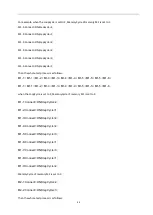
The remote control signal input terminal (SIGNAL IN terminal) is available on the rear panel of the TH7100
series programmable AC power supply. After PLC Onoff of SysCom under <SysSetup> page is set to ON, connect
the remote control device to implement remote control. This terminal is a D-type (9PIN) terminal block male
seat, wit
h output switch and input control of 7 groups of memory groups.
As shown in Figure5-14
Figure 5-14 Remote control chart
ON: The control switch is connected between PIN3 and PIN5
OFF: The control switch is connected between PIN2 and PIN5
MANUAL Mode
:
M1 The control switch is connected between PIN8 and PIN5
M2 The control switch is connected between PIN9 and PIN5
M3 The control switch is connected between PIN8, PIN9 and PIN5
Summary of Contents for TH7105
Page 14: ...9...


