— 73 —
6F3A4768
3.4.6 Sequence Input/Output
3.4.6.1 Sequence Input
The first input data of transmission is specified to sequence data input, then set SERSEQDATA1,
SERSEQDATA2 or SERSEQDATA4. Table 3.4.14 ~ Table 3.4.16 show the bit signals of each sequence input.
In general, a value of 1 indicates either the normal or the operating state, and 0 indicates either an error or
stopped.
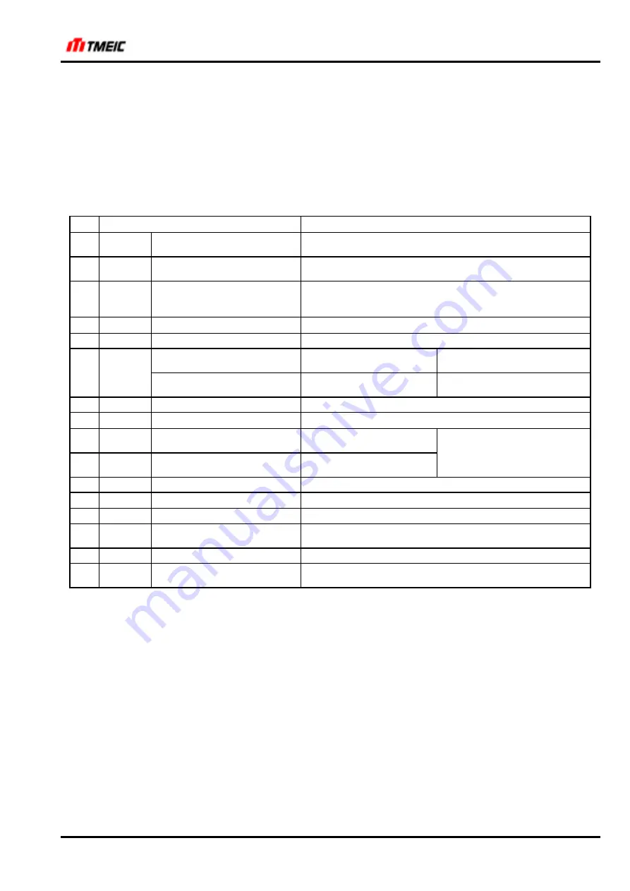
Table 3.4.14 SERSEQDATA1 Bit Signals
Bit Signal
name
Contents
15 IL_
External interlock
1: Operation permitted
Off while running causes a coast stop
14 UVS
External safety switch
1: Operation permitted, contactor closed
Off while running causes a coast stop
13 EXT
Startup command
1: Startup command
Off while running can be selected either a deceleration stop
or a coast stop
12 SPA1
Spare 1
1: Normal
11 BRTST
Brake test
1: Brake released
Torque control selection
1: Tension control,
0: Speed control
When torque control is
selected
10 ST
Load burden share slave
selection
1: Slave (torque control)
When mechanical coupling is
selected
9 F
Forward jog run command
1: Forward jog run command
8 R
Reverse jog run command
1: Reverse jog run command
7 3S
3-speed reference command 1: 3-speed reference
command
(3S, 2S) = (0, 0):
6 2S
2-speed reference command 1: 2-speed reference
command
1-speed reference command
5 B
Brake command
1: Brake release command
4 FLD
Field excitation command
1: Field excitation command (when EXT is off)
3 BC_
Brake close command
0: Brake close
2 HB
Heart beat (transmission
healthy)
Periodical rectangular wave signals
1 EXRST External reset
1: reset request
0 R_TEN
Reverse winding command 1: Reverse winding, 0: Forward winding (Torque direction
when torque is controlled)
StockCheck.com


