— 63 —
6F3A4768
3.4.4.2 Scan Transmission
This transmission system transmits data at specified intervals (at regular time).
There are inputs and outputs as drive equipment. Inputs are command input of the speed reference and the
sequence signal from PLC etc. Outputs are used for transmission of the actual value of speed and current, etc.
from drive equipment to control / surveillance apparatus of upper side, such as PLC.
CAN
The communication protocol of DeviceNet is using a controller area network (CAN).
The Number of Transmission Words
The numbers of transmission words which one station (drive equipment) treats are 4 words receiving / 4
words sending (4W/4W mode), or 4 words receiving / 10 words sending (4W/10W mode).
DeviceNet
Transmission
Mode
The transmission mode of DeviceNet is 4W/4W mode or 4W/10W mode. The transmission mode is set up by
$SCAN_WR_SIZE.
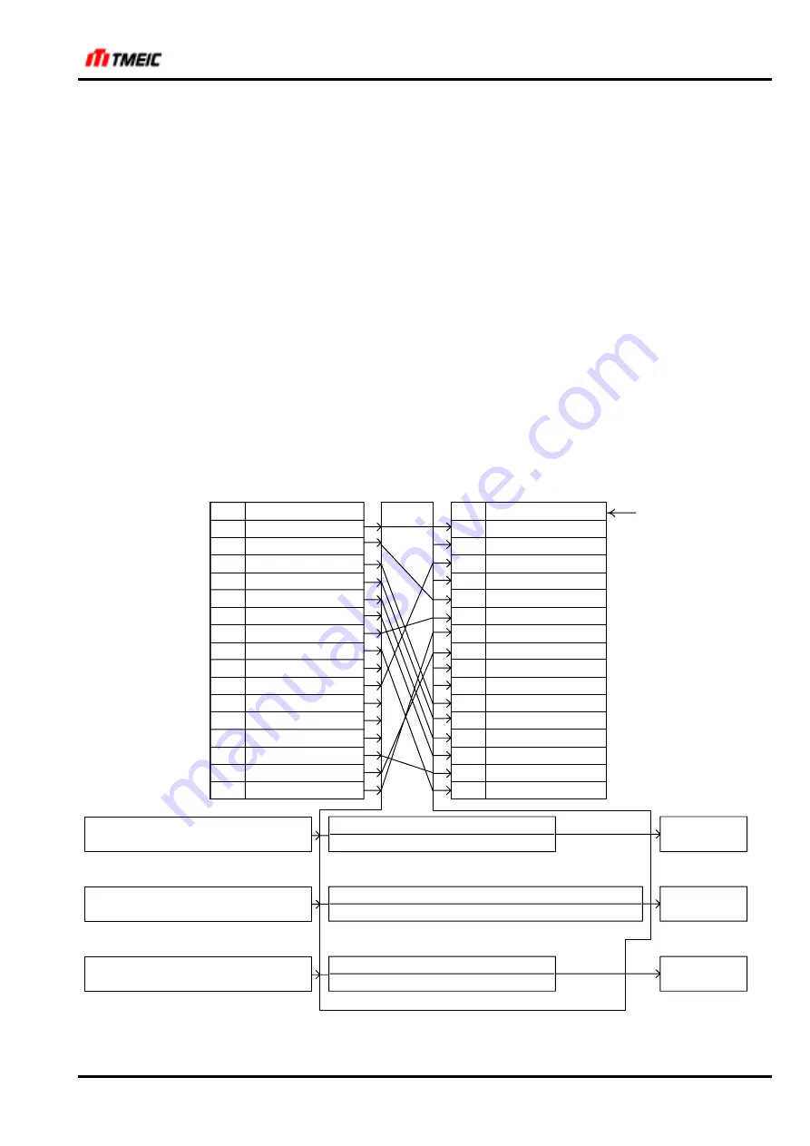
The sending and receiving contents in the case of the 4W/4W mode are shown in
Fig. 3.4.9
and
Fig. 3.4.10
. The
contents of transmission of DeviceNet master (PLC) is based on DeviceNet specifications Volume II Release 1.2
Instance 23 and 73.
BIT
F
E
D
C
B
A
9
8
7
6
5
4
3
2
1
0
SERSEQDATA1
IL_
UVS
EXT
SPA1
BRTST
ST
F
R
3S
2S
B
FLD
BC_
HB
EXRST
R_TEN
BIT
F
E
D
C
B
A
9
8
7
6
5
4
3
2
1
0
Command input
IL_
BRTST
B
FLD
BC
ST
R_TEN
Net Ref
Net Ctrl
Fault Reset
Run Rev
Run Fwd
DeviceNet Master
PLC etc.
DeviceNet slave
Drive equipment
Address defined by
$SCAN_RCV02_AS
Speed Reference [min
-1
] x 2
$DNET_SP_SCALE
25000
2
$DNET_SP_SCALE
x $CS_MOTOR_RPM [min
-1
]
SP_REF1
[25000/100%]
Address defined by
$SCAN_RCV01_AS
Torque Reference [Nm] x 2
$DNET_TR_SCALE
4 x $CS_MOTOR_RPM [min-1] x $CS_SP_BASE [1000/100%]
2
$DNET_TR_SCALE
x 974 x $MA_MOTOR_KW [kW] x 98
Address defined by
$SCAN_RCV03_AS
TENS_R1
[4000/100%]
Process Reference [%] x 2
$DNET_PRC_SCALE
$DNET_PRC_GAIN
2
$DNET_PRC_SCALE
DROOP_GAIN_T
[10000/100%]
Address defined by
$SCAN_RCV04_AS
ex.)
ARND-8127
ex.) SERSEQDATA1, 2, 4
Fig. 3.4.9
DeviceNet 4W/4W Mode (Receive)
StockCheck.com


