— 58 —
6F3A4768
3.4.3.2 Scan Transmission
This transmission system transmits data at specified intervals (at regular time).
There are inputs and outputs as drive equipment. Inputs are command input of the speed reference and the
sequence signal from PLC etc. Outputs are used for transmission of the actual value of speed and current, etc.
from drive equipment to control / surveillance apparatus of upper side, such as PLC.
The Original Protocol of RS485 Driver
The communication protocol of ISBus is using the original protocol of RS485 driver.
The Number of Transmission Words
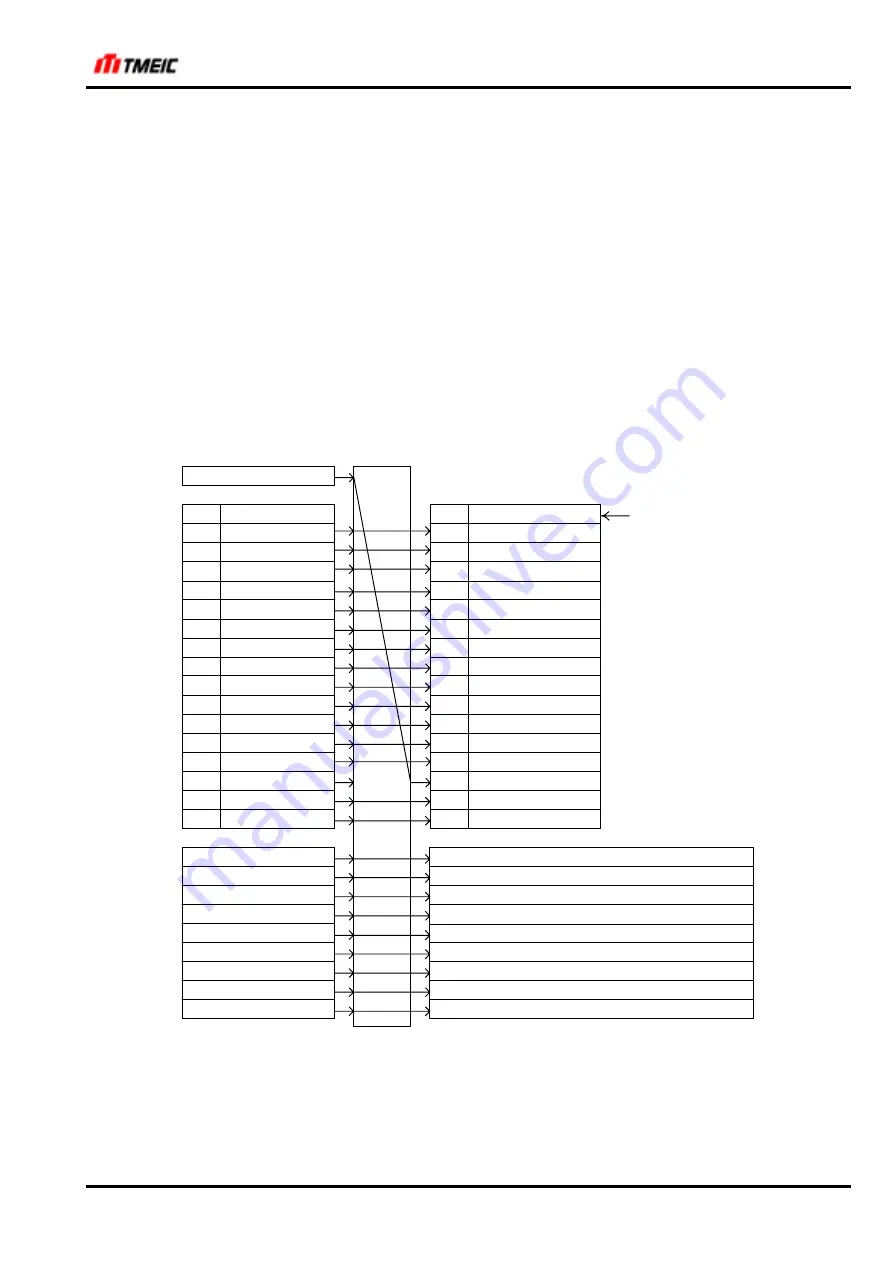
The number of send and receive transmission words which one station (drive equipment) treats are 10 words.
Sending and receiving contents are shown in Fig. 3.4.6 and Fig. 3.4.7. As for the first word, sending and
receiving perform bit transmission inside a transmission board. Although transmission data in ISBus master
(PLC) is 32 bits, these are divided into 16 bits and arranged perpendicularly in Fig. 3.4.6 and Fig. 3.4.7.
BIT
F
E
D
C
B
A
9
8
7
6
5
4
3
2
1
0
SERSEQDATA2
QSTOP
UVS
EXT
CM_BUF1
CM_BUF2
ST
F
R
3S
2S
FLD
HB
EXRST
R_TEN
BIT
F
E
D
C
B
A
9
8
7
6
5
4
3
2
1
0
Transmission 1
QSTOP
UVS
EXT
CM_BUF1
CM_BUF2
ST
F
R
3S
2S
FLD
EXRST
R_TEN
ISBus Master
PLC etc.
ISBus Slave
Drive Equipment
Address defined by
$SCAN_RCV01_AS
Optional address defined by $SCAN_RCV02_AS
Transmission Inp. 2
Transmission Inp. 3
Transmission Inp. 4
Transmission Inp. 5
Transmission Inp. 6
Transmission Inp. 7
Transmission Inp. 8
Transmission Inp. 9
Transmission Inp. 10
Heartbeat
ARND-8204
ex.) SERSEQDATA1, 2, 4
Optional address defined by $SCAN_RCV03_AS
Optional address defined by $SCAN_RCV04_AS
Optional address defined by $SCAN_RCV05_AS
Optional address defined by $SCAN_RCV06_AS
Optional address defined by $SCAN_RCV07_AS
Optional address defined by $SCAN_RCV08_AS
Optional address defined by $SCAN_RCV09_AS
Optional address defined by $SCAN_RCV10_AS
Fig. 3.4.6
ISBus (Receive)
StockCheck.com


