— 115 —
6F3A4768
5.2 Main Circuit Configuration of TMdrive-30
5.2.1 Single Drive (1500kVA, 2000kVA)
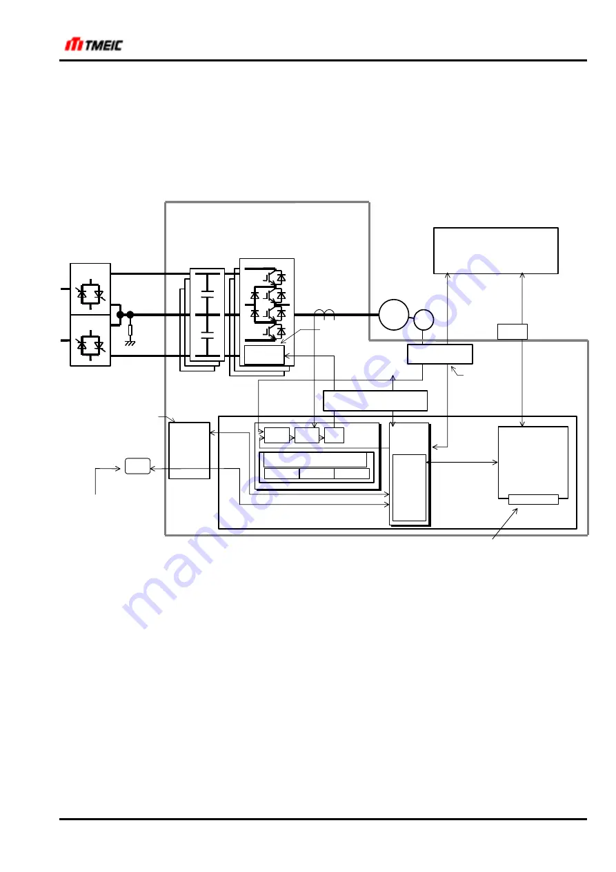
Fig. 5.2.1 shows the circuit configuration of Cabinet type.
The DC power is supplied from the external DC main power supply to the main circuit through the common bus
at the lower portion of the enclosure, and then converted by the inverter into 3-phase AC power necessary to
drive the motor (frequency, voltage, and current are controlled).
PP7
Speed
control
Current
control
PWM
SS
Main control board ARND-3110D
Display unit
KPAD-3122A
(OPTION)
PC
Trunk line
PG resolver
sensor-less
External P-1/O
TOSLINE-S20
ISBus
Profibus
DeviceNet
Windows version
Maintenance tool
1500kVA
2000 kVA
Capacitor unit
Extended transmission
grandchild board
(S-NET)
ARND-8217A (F07)
ARND-8217D(FC)
(ISBus)
ARND-8204A
(Profibus) (optional)
(DeviceNet) (optional)
Trunk line
transmission
Display control
Tool
transmission
Transmission
CPU
SH2
ASC
Basic motor control function
Sensor-less
PG
Resolver
DC common
power
DC common
power
IM
IGBT stack
Gate board
ARND-2711B
Gate board is
common with
T-350W
Internal P-I/O
Extended external P-I/O
External I/O board
ARND-3120
Main circuit interface board
ARND-3138A
Display unit is common
with TMdrive-10
TMdrive-30
Extended transmission grandchild board is common with TMdrive-10
External I/O circuit
is common with
TMdrive-10
Fig. 5.2.1 Wiring Diagram of TMdrive-30 Control (Single:1500kVA, 2000kVA)
The main circuit is composed of a capacitor and an inverter that converts the DC power into AC power. Basically,
the capacitor is intended to temporarily store reactive power of the induction motor. The IGBT unit consists of
three phase IGBT stacks, and the output power is supplied to the motor.
Hole CTs (HCTU and HCTW) are provided on the U-phase and W-phase outputs as current detectors.
StockCheck.com


