background image


— 64 — 

6F3A4768 

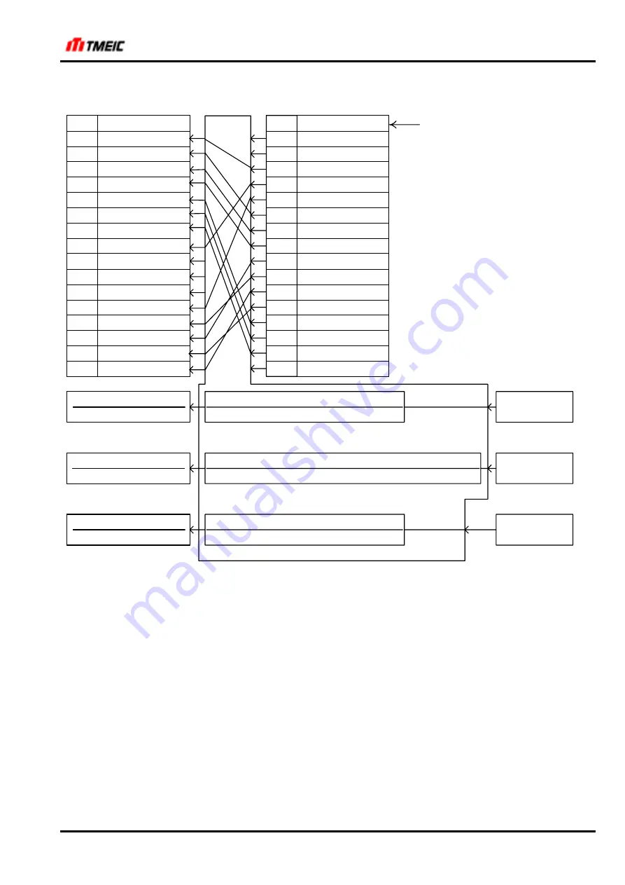
DeviceNet Master

PLC etc.

DeviceNet slave
Drive equipment

Address defined by
$SCAN_WR02_AS

BIT
F
E
D
C
B
A
9
8
7
6
5
4
3
2
1
0

BIT
F
E
D
C
B
A
9
8
7
6
5
4
3
2
1
0

SSEQ_OUT1

BLR
UVA
UV
READY
C_L
RNTD
FLDR
FD
RD
FAULT
ALARM
C_FN
CUT
SP_LMT
HB

Sequence output

UVA
C_L
RNTD
FLDR
C_FN
CUT
SP_LMT
UV
At Reference
Ref From Net
Ctrl From Net
Ready
Running 2 (Rev)
Running 1 (Fwd)
Warning
Faulted

Speed Feedback [min

-1

]

2

$DNET_SP_SCALE

2

$DNET_SP_SCALE 

x $CS_MOTOR_RPM [min

-1

]

25000

SP_F_OUT

[25000/100%]

Address defined by
$SCAN_WR01_AS

Torque Feedback [Nm]

2

$DNET_TR_SCALE

2$DNET_TR_SCALE x 974 x $MA_MOTOR_KW [kW] x 98

4 x $CS_MOTOR_RPM [min-1] x $CS_SP_BASE [1000/100%]

Address defined by
$SCAN_WR05_AS

T_R_OUT

[4000/100%]

Process Feedback [%]

2

$DNET_PRC_SCALE2

2

$DNET_PRC_SCALE

$DNET_PRC_GAIN2

I1_F_DSP

[4000/100%]

Address defined by
$SCAN_WR04_AS

ex.)

ARND-8127

*1
*2

ex.) SSEQ_OUT1, 2, 4

*1) Indefinite value (Do not use At
Reference)
*2) BIT 6: Net Ref of Command input
(See Fig.3.4.7)


Fig. 3.4.10 

DeviceNet 4W/4W Mode (Send) 

StockCheck.com

Summary of Contents for TMdrive-30

Page 1: ...nverter TMdrive 30 TMdrive P30 Instruction Manual Oct 2004 TOSHIBA MITSUBISHI ELECTRIC INDUSTRIAL SYSTEMS CORPORATION TM_F50000B TOSHIBA MITSUBISHI ELECTRIC INDUSTRIAL SYSTEMS Corporation 2004 All Rights Reserved S t o c k C h e c k c o m ...

Page 2: ...zed knowledge Read this manual completely and carefully before using this equipment Personnel who use this equipment should undergo specialized training provided by our TMEIC on a for fee basis Contact your TMEIC representative for details on training courses S t o c k C h e c k c o m ...

Page 3: ...ontrol Specifications Speed sensor PLG 23 2 3 5 TMdrive P30 Control Specifications Speed sensor Resolver 24 2 3 6 TMdrive 30 Control Specifications Speed Sensor less Vector Control 25 2 3 7 TMdrive 30 Control Specifications Speed Sensor less Vector Control with Driving Multiple Motors 26 2 3 8 TMdrive 30 Control Specifications V f control 27 2 3 9 TMdrive 30 Control Specifications 28 2 3 10 Rating...

Page 4: ... 3 Optional Sequence Output 78 3 4 7 Serial Input Output Signals 79 3 4 7 1 Serial Input Signals 79 3 4 7 2 Serial Output Signals 80 3 4 8 Message Transmission 81 3 4 9 Transmission Error Detection 81 3 4 9 1 Heartbeat 83 3 5 P I O Input output 84 3 5 1 P I O Input 84 3 5 2 P I O Output 88 3 6 Transmission Between Drives 89 3 7 Motor Temperature Detection Circuit TMdrive 30 89 3 8 Analog Input Out...

Page 5: ... 5 4 3 2 IQ Limit 129 5 4 4 D Q Axis Current Control 130 5 4 5 Voltage Reference 132 5 4 6 Speed Feedback 133 5 4 6 1 PLG 133 5 4 6 2 Resolver 134 5 5 Optional Function According to Application TMdrive 30 135 5 5 1 Auto Field Weakening Control 135 5 5 2 Torque Control 136 5 5 3 Sensor less Vector Control 139 5 5 4 V f Control 139 5 5 5 JOG Operation 140 5 5 6 Emergency Operation 141 5 5 6 1 Emerge...

Page 6: ...ve 30 and TMdrive P30 160 7 1 Setting Data 160 8 Fault and Recovery Common to TMdrive 30 and TMdrive P30 161 8 1 Cautions when Handling Fault 161 8 2 Traceback 162 8 3 How to Repair 163 8 3 1 Cautions on Repair 163 8 3 2 Replacing Units 163 8 4 Restoring Setting Parameters 163 8 4 1 Reloading Personal Computer Tool 163 S t o c k C h e c k c o m ...

Page 7: ...ead to injury albeit of a somewhat lesser severity Failure to follow these directions may also lead to property loss such as damage to the equipment or components or to fires Electric shock warning Warning for safe work DANGER Hazardous voltage can result in electric shock Make sure that there is no electrical charge before inspection or maintenance WARNING Hazardous voltage can result in electric...

Page 8: ...ls These labels present items related to maintaining the performance of the equipment NOTICE When operating or adjusting the equipment and during maintenance inspections be sure to observe the precautions noted in the User s Manual The following are guidelines for the replacement of parts PARTS GUIDELINES FOR REPLACEMENT COOLING FAN 3 YEARS ELECTROLYTIC CAPACITOR 7 YEARS POWER SUPPLY UNIT 7 YEARS ...

Page 9: ...or more 1800 V dc or more and 200 V ac or 220 230 V ac circuits which are extremely dangerous Do not remove the protective covers designed for shock prevention at any time other than inspection and maintenance Do not touch internal parts with wet hands Do not touch the inside panel or parts of the equipment while the power is being applied or the motor is running S t o c k C h e c k c o m ...

Page 10: ...least five minutes 5 Make sure that the charge lamp on the inverter panel is off 6 Turn off the control power supply MCCB CONTROL 7 Unlock the door padlock 8 Remove the screws two places on the front door of the inverter panel and open the door with the door handle 9 Use a voltage checker and the like to check that the main circuit and the control circuit are already discharged 10 Measure the volt...

Page 11: ...el and tighten the screws two places 7 Lock the door padlock 8 Turn on the control power supply MCCB CONTROL Note Check that there is no error detected 9 Check that Fault or Alarm isn t displayed on the operation panel on the automatic control panel If Fault or Alarm is displayed check the fault message and then recovery it 10 Turn on the DC power supply unit main power Note When a common DC power...

Page 12: ... panel is off 6 Turn off the control power supply MCCB CONTROL The OFF LED on the automatic control panel turns off unlit 7 Unlock the door padlock 8 Remove the screws two places on the front door of the converter panel and open the door with the door handle 9 Use a voltage checker and the like to check that the main circuit and the control circuit are already discharged 10 Turn off the control po...

Page 13: ... displayed check the fault message and then recovery it 10 Check the safety of the system and release of the operation prohibited on the hardware safety or emergency stop switch etc 11 When the AC MAIN CIRCUIT BREAKER switch on the automatic control panel is turned on the pre charge automatically starts If pre charge does not start examine the items for which the electrical condition UV is not sat...

Page 14: ...tor again As for the rotational direction of the motor the forward rotational direction differs depending on the machine to drive See the schematic diagram To reverse the rotational direction set the polarity of the speed reference to negative To reverse the rotational direction forward rotation by the positive speed reference reverse the polarity of the setting value of CS_MOTOR_RPM turn off the ...

Page 15: ...g procedure Refer to the operation manual of the support tool for the usage of a step response function 1 Check the operation of the drive equipment is off The drive equipment cannot enter the test mode while that is in operation 2 Select a required test mode by using step response function of the support tool When the test mode is chosen the drive equipment enters the test mode panel ready lump i...

Page 16: ...T NOW 2 Collect the trace back data Collect the data recorded in the non volatile memory in the unit The latest 6 or 7 portions of trace back data are stored PC that maintenance tool is installed option can replay the trace back data 3 Check the apparent operating state of the equipment Perform the safety check described earlier before performing this check In addition to recover from the fault se...

Page 17: ...405 GATE_U_B 76 F_VN_B 161 UVD_B 250 UVNSIL 339 C_FN_B 406 GATE_V_B 77 F_WN_B 167 C_FN_T_B 251 ACSW_C_B 340 OH_ACL 407 GATE_W_B 82 OSS 170 DCSW_B 253 M_FN 341 MTMP_S 409 SPA3 83 OSS_FO 171 AC_MCCB_B 254 SP_SIL 342 M_OH 410 VDC_IL 86 SP_ERR 176 UVP_B 255 STCMD 343 M_OH_A 411 PRE_CTT_IL 87 SP_ERR2 177 UVN_B 256 GDM_F_U 344 OL_A 412 ACP 89 CURU 178 UVP 257 GDM_F_V 345 CL_TA 413 UVPSIL 90 CURW 179 UVN...

Page 18: ...ous values will be restored the next time the system is initialized The write operation that saves the parameters from RAM to EEPROM may require up to dozens of seconds to complete In addition user comments can be attached to the setting value stored in EEPROM Write time differs depending on the number of parameters and thus make sure to wait until the user comment will be registered displayed on ...

Page 19: ...ult and recovery maintenance points and describes maintenance and operation after the installation of the equipment Interfaces For the connections with external equipment read 3 Interface Concept of control To know how this equipment performs variable speed control over motors read 5 Operation Startup and operation of equipment For the procedure for preparations before starting the equipment and h...

Page 20: ...n process In this equipment as the control power is turned from off to on the data and circuits are initialized Interface A method that exchanges signals between this equipment and external equipment Inverter A reverse conversion circuit that converters DC main power voltage into AC voltage DC AC conversion Inverter unit A box containing IGBT inverter circuit and gate drive circuit board Converter...

Page 21: ...tor or high resolution brushless resolver can be used as a speed detector installed in the motor Speed sensor less vector control is also possible 6 High power factor TMdrive P30 high efficiency A high efficiency drive system can be constructed due to high efficiency achieved by sine wave PWM control and small device loss Because TMdrive P30 can control the power waveform as sine wave it reduces p...

Page 22: ...th varies with inverter capacity Panel Type TMEIC panel enclosure Protection structure type Semi closed enclosure IP20 Conforms to JEM 1267 1975 1 IP32 Enclosure plate thickness Door 2 3 mm Rear and side panels 1 6 mm Paint color Enclosure JEM1135 1982 5Y7 1 Channel base and hoist angle N1 5 Internal panels are not painted except some specific area 1 Other specified color Only for enclosure Coatin...

Page 23: ...ter Grounding protection Detection Not provided TMdrive 30 Provided TMdrive P30 Other Schematic diagram code IEC 60617 JIS C0301 Group 1 Display unit Standard or high function type selection Standard unit Display 7 segment LED 3 Operation unit Fault reset switch Panel interlock switch Status display LED 3 Other Tool I F connector High function unit Display Monochrome display graphic module 240 64 ...

Page 24: ... pulse signals as PLG input Max 10kHz Speed control range 0 to 100 Torque is limited at very low speed Speed control accuracy Rated speed 100 0 01 with digital input 0 1 with analog input Speed setting resolution 1 25000 digital setting 1 1000 or more analog setting Speed response ωc 60 rad s Max Torque control range 0 to 100 Torque control accuracy 30 without R2 compensation 3 with R2 compensatio...

Page 25: ...lable to output 2 n pulse Speed control range 0 to 100 Torque is limited at very low frequency Speed control accuracy Rated speed 100 0 01 with digital input 0 1 with analog input Speed setting resolution 1 25000 digital setting 1 1000 or more analog setting Speed response ωc 60 rad s Max Torque control range 0 to 100 Torque control accuracy 30 without R2 compensation Optional 3 with R2 compensati...

Page 26: ...in 1 Max Number of motors to drive One unit Speed sensor None Speed control range 3 to 100 Torque is limited at very low frequency Speed control accuracy Rated speed 100 0 5 with digital input 0 5 with analog input Speed setting resolution 1 25000 digital setting 1 1000 or more analog setting Speed response ωc 20 rad s Max Torque control range Not applicable Torque control accuracy R2 compensation...

Page 27: ...esponse ωc 15 rad s Max Torque control range Not applicable Torque control accuracy R2 compensation Torque compensation with motor temperature sensor Compensation is possible with one representative unit Motor overheat protection is possible Field weakening range Base speed Top speed 1 1 2 Current response ωc 1000 rad s Max Current control accuracy 2 Minimum number of units to drive Not provided P...

Page 28: ...al specification Required hardware None Output frequency range 0 0 to 120 Hz 0 0 to 120Hz Motor rotation speed 4 poles 3600 min 1 Max 2 poles 7200 min 1 Max Speed sensor None Speed control None Speed setting resolution 1 25000 digital setting 1 1000 or more analog setting Current control None Current limit function Equipped Current limit 0 400 Slip frequency compensation Equipped Rated slip freque...

Page 29: ...Item Standard specification Optional specification Basic control method Voltage control power factor control dp axis current control Voltage control range AC input voltage effective value x 2 or more 1800Vdc or less Voltage control accuracy 5 Voltage response ωc 60rad s max Restart at instantaneous power failure Not provided Provided S t o c k C h e c k c o m ...

Page 30: ...drive P30 Ratings Table Standard Specifications Frame size Output capacity kVA DC voltage Vdc AC voltage Vac Rated input current Arms Rated output current Adc Generated loss kW Input power factor 2000 1700 2 900 1100V 10 929 944 34 0 95 or more 4000 2 1700 2 900 1100V 10 2 929 2 944 2 34 0 95 or more Where the rated input current is a value when input voltage 1100Vac input power factor 0 98 Device...

Page 31: ...1200Vac Table 2 3 12 Ratings with over load level TMdrive 30 Table 2 3 13 Ratings with over load level TMdrive P30 Frame DC voltage AC voltage Rated AC current Arms Vdc Vac OL150 60s OL175 60s OL200 60s OL250 60s OL300 60s 1500 693 594 520 416 347 2000 924 792 693 554 462 3000 1386 1188 1040 832 693 4000 1800 1250 1848 1584 1386 1109 924 Frame DC voltage AC voltage Rated AC current Arms Vdc Vac OL...

Page 32: ...ltage signals but also by protection detection in the control circuit M Main Control CPU Gate Control Board GDM_F OS SP_ERR CL_T ASPR Limit ACR PWM TOSLINE S20 TL_F STALL OL5 OL20 OVP N SS F_U C_FN_T OH_T Thermal switch M_FN M_OH M_OH_A CL_TA OL_A C_FN OCA ACSW M_FN_T MTMP_S UVP N OCD BR_F Brake Circuit OSS_F0 CP_PSF Tmp SP_ERR2 Option F_V F_W F_C Fig 2 3 2 TMdrive 30 Protection System Diagram S t...

Page 33: ... Limit ACR PWM TOSLINE S20 TL_F OVP N F_U C_FN_T OH_T Thermal switch CL_TA C_FN UVP N OCD CP_PSF F_V F_W F_C OL5 OL20 OL_A OCA PRE CHARGE CIRCUIT PRE CHARGE CIRCUIT F_PRE F_GND PRE_F GR GR_T Fig 2 3 3 TMdrive P30 Protection System Diagram S t o c k C h e c k c o m ...

Page 34: ...tion OL5 OL20 OL_A 5 minute and 20 minute RMS computation of the output current is performed and when the predetermined value is exceeded activated 5 minute RMS setting or 20 minute RMS setting is provided CP_RMS_5 5 minute RMS protection CP_RMS_20 20 minute RMS protection CP_RMS_A5 5 minute RMS alarm CP_RMS_A20 20 minute RMS alarm Example The equipment allows the following operation pattern There...

Page 35: ... detection 2 3 11 4 Control Circuit and Power Supply 1 Control power supply failure CPSF Activated when the control power supply drops below the control power loss detection level The higher the setting level the shorter the time it takes to detect control power loss In the standard setting PSF 140 0 V is set when restart at power failure optional is not provided and 160 0 V is set when restart at...

Page 36: ...age expansion at grounding accident occurrence A blown fuse is detected by the microswitch 2 3 11 5 Protection Associated with Motor and Break TMdrive 30 1 Motor overheat M_OH M_OH_A When a temperature sensor is provided optional for the motor temperature is detected to protect the motor The standard setting is CP_MOTOR_OH 155 C An M_OH_A alarm is activated at 10 C lower fixed than this setting va...

Page 37: ...ated protection TMdrive P30 1 Converter grounding detection GR GR is detected when abnormal current is detected in the grounding circuit that is grounded with main circuit via high resistance 2 Converter grounding detection timer GR_T Activated when abnormal current is detected in the grounding circuit The common use is that an alarm is output to outside with a GR signal and the equipment is stopp...

Page 38: ...cal ready condition UVA_EXT Yes Yes Yes Equipment ventilation fan stop timer C_FN_T Yes Yes TIME_CFAN Control power source failure CPSF Yes Yes CP_PSF Current limit timer CL_T Yes Yes TIME_CL DC voltage drop P N UVP VVN Yes Yes Yes Overload 5 min OL5 Yes Yes Yes CP_RMS_5 CP_RMS_A Overload 20 min OL20 Yes Yes Yes CP_RMS_20 CP_RMS_A20 Equipment overheat timer OH_T Yes Yes TIME_OH Output open AC_NL Y...

Page 39: ...synchronization PLL error PLL Yes Yes Yes Equipment overheat timer OH_T Yes Yes Yes TIME_OH External interlock IL Yes Yes Transmission error TL_F1 4 Yes Yes External equipment electrical ready condition UVA_EXT Yes Yes Equipment ventilation fan stop timer C_FN_T Yes Yes TIME_CFAN Control power source failure CPSF Yes Yes CP_PSF Current limit timer CL_T Yes Yes TIME_CL DC voltage drop P N UVP VVN Y...

Page 40: ... Frame size S V classification 1 S V classification 2 5 TMdrive 30 Enter the panel structure Enter the output voltage class Enter the frame size Specify whether special specifications are required or not C 1200V system 1500 152 Blank Standard J Japanese model 2000 202 Blank Standard 3000 302 4000 402 V Special specifications are applied Specify when job No is issued Indication range of nameplate P...

Page 41: ...assification 1 S V classification 2 G TMdrive P3 0 Enter the panel structure Enter the input voltage class Enter the frame size Specify whether special specifications are required or not C 1200V system 2000 202 Blank Standard J Japanese model Blank Standard 4000 402 V Special specifications are applied Specify when job No is issued Indication range of nameplate Product code example VT3GJC202 VT3G ...

Page 42: ...z or 200Vac 50Hz 3 1 2 Grounding Fig 3 1 1 shows the recommended grounding circuit of TMdrive 30 and TMdrive P30 with associated units TMdrive 30 and TMdrive P30 are normally used together and the common DC bus bar is used to connect between these two drive units In this configuration ground bus bar is also provided to connect between them This equipment should be grounded in the following way Con...

Page 43: ...tral point Drive unit control ground trunk line a2 Connect the drive unit ground from the panel enclosures to the control ground trunk line ED at one point a1 Connect the drive unit ground from the panel enclosures to the main circuit ground trunk line EHT at one point Ground it from the converter panel enclosure whenever possible f When adding a drive unit to the existing ones install a ground tr...

Page 44: ...en connecting to the motor use a shielded cable and be sure to connect it to the grounding conductor on both the drive unit side and motor side 3 2 1 One Motor Connect the output terminals U V W of the equipment and motor terminals R S T At this time connect the output terminals of the equipment and motor terminals U R V S W T as they are irrespective of the rotation direction of the motor The rot...

Page 45: ...lected so that the PLG output pulse frequency at the maximum speed satisfies Equation 3 3 1 If it exceeds the specified range the pulse may not be recognized causing the control not to be done Equation 3 3 1 3300 Hz rated motor speed min 1 60 x PLG pulse count P rev 100000 Hz When using a PLG as speed sensor pulse count of PLG output depends on the pulse count of the speed sensor and they become t...

Page 46: ...rity by changing the resolver wiring Table 3 3 3 shows the relationship between the equipment parameter setting and rotating direction Table 3 3 2 Specified Cables for Resolver Manufacturer Specification No Cable specifications Showa Densen WS82 1066 KMPEV CU 4 P 2 mm 2 Fujikura Densen II 35122 TPK88 1001 IPEV S Cu 4 P 2 mm 2 Furukawa Denko HT 880320 TPK88 2001 KPEV S Cu 4 P 2 mm 2 Mitsubishi Denk...

Page 47: ...stationary type 4x d TS2113 series stationary type 1x Drive unit ARND 3120B C D TB1 6 TB1 7 TB1 8 TB1 9 TB1 2 TB1 3 TB1 5 TB1 4 TB1 1 Exsin EXcos Sin cos Drive unit ARND 3120B C D TB1 6 TB1 7 TB1 8 TB1 9 TB1 2 TB1 3 TB1 5 TB1 4 TB1 1 Exsin EXcos Sin cos Drive unit ARND 3120B C D TB1 6 TB1 7 TB1 8 TB1 9 TB1 2 TB1 3 TB1 5 TB1 4 TB1 1 Exsin EXcos Sin cos Drive unit ARND 3120B C D TB1 6 TB1 7 TB1 8 TB...

Page 48: ... drive multiple motors in parallel For example it is not possible to drive 20 motors with 10 motors in each bank 2 Motors running in parallel must have the same rating and the load devices of the motors must have the same moment of inertia GD2 If different rating motors are included or the load condition changes continuously GD2 is different parallel operation is not possible 3 When motors are run...

Page 49: ... it exceeds 10 kHz this may cause the pulses not to be transmitted 1 1x type resolver is used CS_RES_TYPE 1 CS_PGOUT Any of 64 128 256 512 and 1024 is set Example When the 100 speed is 1800 min 1 CS_PGOUT is determined so that 1800 60 x CS_PGOUT 10000 is satisfied CS_PGOUT 10000 1800 60 333 Therefore CS_PGOUT 256 2 4x type resolver is used CS_RES_TYPE 4 CS_PGOUT Any of 256 512 1024 2048 and 4096 i...

Page 50: ...fied stations at irregular time This system is applicable to transmission of a lot of data such as trace back data if a fault occurs This transmission corresponds by TOSLINE S20 transmission and ISBus transmission In TOSLINE S20 transmission it is an option by system specification 3 Transmission unit Unit of transmission data is called word 1 word is 16 bits 1 word of the number of scan memory wor...

Page 51: ...ry words 4 words send and receive unit 4 words send and 10 words receive unit Transmission speed of scan transmission 125 kbps 256 kbps 500 kbps Frame size of message transmission Not supported Table 3 4 4 Overview of PROFIBUS PROFIBUS Cable type A Maximum number of stations Master or drive station 32 units with repeater Master or drive station 99 units without repeater Scan memory words 6 words s...

Page 52: ... 1 km Overall length 10 km or less Same as left Applicable ASC model ASC25 SASC25 US FC connector 2 ch F07 connector 8 ch ASC22 SASC22 US FC connector 10 ch 1 The cable with which wavelength specification differs cannot be used Use ASC25 Active Star Coupler to connect this standard specification TOSLINE S20 and PLC 3 4 2 1 TOSLINE S20 Connections The connections may vary depending on the type of c...

Page 53: ... they are not duplicated The transmission system of the TOSLINE S20 transmits data on this DPRAM to all stations at specified intervals this interval may vary depending on the number of stations connected The data is then written to the DPRAM on each station The same data on this DPRAM is then made on all stations Therefore this system is called common memory Use of the scan transmission makes it ...

Page 54: ...dto Drive 2 Input 6 W Output 10 W Memoryallocatedto Drive n Input 6 W Output 10 W TOSLINE S20 PLC System master equipment FC Connector Memory allocatedtoDrive 1 Input 6 W Output 10 W Memory allocatedtoDrive 2 Input 6 W Output 10 W Memory allocatedtoDrive n Input 6 W Output 10 W Transmission Memory allocatedtoDrive 1 Input 6 W Output 10 W Memory allocatedtoDrive 2 Input 6 W Output 10 W Memory alloc...

Page 55: ...SCAN_W_ADRS 9 Optional Address defined by SCAN_RCV01_AS Optional Address defined by SCAN_RCV02_AS Optional Address defined by SCAN_RCV03_AS Optional Address defined by SCAN_RCV04_AS Optional Address defined by SCAN_RCV05_AS Optional Address defined by SCAN_RCV06_AS Optional Address defined by SCAN_RCV07_AS Optional Address defined by SCAN_RCV08_AS Optional Address defined by SCAN_RCV09_AS Optional...

Page 56: ...nal Address assigned by SCAN_RCV02_AS Optional Address assigned by SCAN_RCV03AS Optional Address assigned by SCAN_RCV04_AS Optional Address assigned by SCAN_RCV05_AS Optional Address assigned by SCAN_RCV06_AS Optional Address assigned by SCAN_RCV07_AS Optional Address assigned by SCAN_RCV08_AS Optional Address assigned by SCAN_RCV09_AS Optional Address assigned by SCAN_RCV10_AS Optional Address as...

Page 57: ... address of receive data 0 to 127 TL S20 high speed version transmission SCAN_RCV01_AS Receiving address 1 SERSEQDATA1 SERSEQDATA2 Sequence signal input Usage is fixed SCAN_RCV02_AS to SCAN_RCV06_AS Receiving address 2 to 6 Specifies data to store received data When SCAN_R_SIZE 6 is set 5 data can be set freely When not used Enter DUST Receiving word data SCAN_RCV07_AS to SCAN_RCV10_AS Receiving a...

Page 58: ...ctor type RJ45 Connector Cable specification Shielded twisted pair cable Bus scan time Number of node Bus scan time ms 2 4 1 5 8 2 6 16 4 17 32 8 3 4 3 1 ISBus Connection Example of connection is shown in Fig 3 4 5 ARND 8204A RX TX Drive Equipment ARND 8204A RX TX ARND 8204A RX TX ISBus Master TX RX Drive Equipment Drive Equipment Fig 3 4 5 Examples of ISBus Connection S t o c k C h e c k c o m ...

Page 59: ...a in ISBus master PLC is 32 bits these are divided into 16 bits and arranged perpendicularly in Fig 3 4 6 and Fig 3 4 7 BIT F E D C B A 9 8 7 6 5 4 3 2 1 0 SERSEQDATA2 QSTOP UVS EXT CM_BUF1 CM_BUF2 ST F R 3S 2S FLD HB EXRST R_TEN BIT F E D C B A 9 8 7 6 5 4 3 2 1 0 Transmission 1 QSTOP UVS EXT CM_BUF1 CM_BUF2 ST F R 3S 2S FLD EXRST R_TEN ISBus Master PLC etc ISBus Slave Drive Equipment Address def...

Page 60: ...onal address defined by SCAN_WR02_AS Optional address defined by SCAN_WR03_AS Optional address defined by SCAN_WR04_AS Optional address defined by SCAN_WR05_AS Optional address defined by SCAN_WR06_AS Optional address defined by SCAN_WR07_AS Optional address defined by SCAN_WR08_AS Optional address defined by SCAN_WR09_AS Optional address defined by SCAN_WR10_AS Heartbeat ARND 8204 ex SSEQ_OUT1 2 ...

Page 61: ...ds setting 10 Fixed SCAN_R_ADRS Start address of receive data 16 Fixed SCAN_RCV01_AS Receiving address 1 SERSEQDATA2 Sequence signal input Set sequence signal input of Bit 2 HB Receiving word data SCAN_RCV02_AS SCAN_RCV10_AS Receiving address 2 to 10 Specifies data to store received data Ex SP_REF1 When not used set DUST SCAN_W_SIZE Number of send words setting 10 Fixed SCAN_W_ADRS Start address o...

Page 62: ... twisted power source 15 Black Red Foil stitch shielded drain wire 18 Open wire Drop line One pair of twisted signal 24 Blue White One pair of twisted power source 22 Black Red Foil stitch shielded drain wire 22 Open wire Depending on transmission speed Transmission speed kbps Maximum trunk cable length m Maximum drop cable length m 125 500 m 100 m 250 250 m 100 m Transmission distance 500 100 m 1...

Page 63: ...6F3A4768 Drive equipment ARND 8127A T3H DN311 or DN311A Scaner Power DC 24 V Drop cable Trunk cable T PDS Tool Drive equipment ARND 8127A Fig 3 4 8 Examples of DeviceNet Connection S t o c k C h e c k c o m ...

Page 64: ...ing contents in the case of the 4W 4W mode are shown in Fig 3 4 9 and Fig 3 4 10 The contents of transmission of DeviceNet master PLC is based on DeviceNet specifications Volume II Release 1 2 Instance 23 and 73 BIT F E D C B A 9 8 7 6 5 4 3 2 1 0 SERSEQDATA1 IL_ UVS EXT SPA1 BRTST ST F R 3S 2S B FLD BC_ HB EXRST R_TEN BIT F E D C B A 9 8 7 6 5 4 3 2 1 0 Command input IL_ BRTST B FLD BC ST R_TEN N...

Page 65: ...Feedback min 1 2 DNET_SP_SCALE 2 DNET_SP_SCALE x CS_MOTOR_RPM min 1 25000 SP_F_OUT 25000 100 Address defined by SCAN_WR01_AS Torque Feedback Nm 2 DNET_TR_SCALE 2 DNET_TR_SCALE x 974 x MA_MOTOR_KW kW x 98 4 x CS_MOTOR_RPM min 1 x CS_SP_BASE 1000 100 Address defined by SCAN_WR05_AS T_R_OUT 4000 100 Process Feedback 2 DNET_PRC_SCALE2 2 DNET_PRC_SCALE DNET_PRC_GAIN2 I1_F_DSP 4000 100 Address defined b...

Page 66: ...RSEQDATA1 IL_ UVS EXT SPA1 BRTST ST F R 3S 2S B FLD BC_ HB EXRST R_TEN BIT F E D C B A 9 8 7 6 5 4 3 2 1 0 Command input IL_ BRTST B FLD BC ST R_TEN Net Ref Net Ctrl FaultReset Run Rev Run Fwd DeviceNet Master PLC etc DeviceNet slave Drive equipment Address defined by SCAN_RCV01_AS Optional address defined by SCAN_RCV02_AS Optional address defined by SCAN_RCV03_AS Optional address defined by SCAN_...

Page 67: ...WR03_AS Optional address defined by SCAN_WR04_AS Optional address defined by SCAN_WR05_AS Optional address defined by SCAN_WR06_AS Optional address defined by SCAN_WR07_AS Optional address defined by SCAN_WR08_AS Optional address defined by SCAN_WR09_AS Optional address defined by SCAN_WR10_AS Option1 Receive Data Option2 Receive Data Option3 Receive Data Option4 Receive Data Option5 Receive Data ...

Page 68: ...W_ADRS Start address of send data 0 Fixed SCAN_WR01_AS Sending address 1 SP_F_OUT Speed feedback SCAN_WR02_AS Sending address 2 SSEQ_OUT1 Sequence signal output SCAN_WR03_AS Sending address 3 DUST Do not use SCAN_WR04_AS Sending address 4 Specifies data to store received data Ex I1_F_DSP When not used set DUST SCAN_WR05_AS Sending address 5 T_R_OUT Torque Sending word data SCAN_WR06_AS SCAN_WR10_A...

Page 69: ...dress 1 SSEQ_OUT1 Sequence signal output Sending word data SCAN_WR02_AS SCAN_WR10_AS Sending address 2 10 Specifies data to store received data Ex SP_F_OUT When not used set DUST TL_OP_ST1 TL_OP_ST4 Drive to Drive transmission opponent station number 0 Do not use Drive to drive transmission TL_OP_DT1 TL_OP_DT4 Drive to Drive transmission opponent word data address DUST Do not use 0 125 kbps 1 250 ...

Page 70: ...stance Diameter Cross section 135 165 Ω 30 pf m 110 Ω km 0 64 mm 0 34 mm 2 Transmission distance Depending on transmission speed Transmission speed kbps Maximum length per segment m 9 6 19 2 45 45 93 75 1200 m 187 5 1000 m 500 400 m 1500 200 m 3000 6000 12000 100 m 3 4 5 1 PROFIBUS Connection Example of connection is shown in Fig 3 4 13 Drive equipment ARND 8130A T3H T3H PROFIBUS master T PDS tool...

Page 71: ...CAN_RCV03_AS Optional address defined by SCAN_RCV04_AS Optional address defined by SCAN_RCV05_AS Optional address defined by SCAN_RCV06_AS PZD1 PZD2 PZD3 PZD4 PZD5 PZD6 Optional address defined by SCAN_WR01_AS Optional address defined by SCAN_WR02_AS Optional address defined by SCAN_WR03_AS Optional address defined by SCAN_WR04_AS Optional address defined by SCAN_WR05_AS Optional address defined b...

Page 72: ...V05_AS Optional address defined by SCAN_RCV06_AS PZD2 PZD3 PZD4 PZD5 PZD6 BIT F E D C B A 9 8 7 6 5 4 3 2 1 0 BIT F E D C B A 9 8 7 6 5 4 3 2 1 0 Address defined by SCAN_WR01_AS SSEQ_OUT1 BLR UVA UV READY C_L RNTD FLDR FD RD FAULT ALARM C_FN CUT SP_LMT HB ZSW RNTD UV SP_LMT HBT C_L CUT ALARM FAULT READY Optional address defined by SCAN_WR02_AS Optional address defined by SCAN_WR03_AS Optional addr...

Page 73: ...R_ADRS Start address of receive data 32 Fixed in use Specifies data to store received data Free setting Available in mode 4 TL_SELF_NO 4 When not used set DUST SCAN_RCV01_AS Receiving address 1 SERSEQDATA1 Sequence signal input Fixed in mode 5 TL_SELF_NO 5 SCAN_RCV02_AS SCAN_RCV06_AS Receiving address 2 6 Specifies data to store received data Set 5 data freely in case that SCAN_R_SIZE 6 When not u...

Page 74: ... a coast stop 12 SPA1 Spare 1 1 Normal 11 BRTST Brake test 1 Brake released Torque control selection 1 Tension control 0 Speed control When torque control is selected 10 ST Load burden share slave selection 1 Slave torque control When mechanical coupling is selected 9 F Forward jog run command 1 Forward jog run command 8 R Reverse jog run command 1 Reverse jog run command 7 3S 3 speed reference co...

Page 75: ...ue control is selected 10 ST Load burden share slave selection 1 Slave torque control When mechanical coupling is selected 9 F Forward jog run command 1 Forward jog run command 8 R Reverse jog run command 1 Reverse jog run command 7 3S 3 speed reference command 1 3 speed reference command 3S 2S 0 0 6 2S 2 speed reference command 1 2 speed reference command 1 speed reference command 5 N U Not used ...

Page 76: ...peed reference command 1 3 speed reference command 8 R_TEN Reverse winding command 1 Reverse winding 0 Forward winding Torque direction when torque is controlled 7 ST Torque control selection 1 Tension control 0 Speed control 6 LB Load barance between stands1 Load balance control 5 N U Not used 4 N U Not used 3 N U Not used 2 UVS External safety switch 1 Operation permitted contactor closed Off wh...

Page 77: ...M Slight fault 1 Slight fault 3 C_FN Cooling fan stopped 1 Cooling fan stopped 2 CUT Discontinuation detecting 1 Discontinuation detected 1 SP_LMT Speed limit 1 Speed limiting 0 HB Heart beat transmission healthy Periodic rectangular wave signals Table 3 4 18 SSEQ_OUT2 Bit Signals Bit Signal name Contents 15 BLR Electrical critical fault 1 Electrical critical fault 14 UVA Electrical condition read...

Page 78: ...Discontinuation detected 10 READY Operation ready 1 Operation ready 9 F_LMT Forward limit 1 Forward limit 8 UV Electrical condition 1 Condition met 7 FLDR Field energized 1 Field energized current running 6 QSTOP Emergency stop 1 Emergency stop 5 BA Brake answer 1 Brake open 4 STALL Low frequency overload 1 Low frequency overload 3 RNTD Running 1 Running 2 C_L Current limit 1 Current limiting 1 OL...

Page 79: ...it detection 12 N U Not used 11 N U Not used 10 N U Not used 9 BA Brake answer 1 Release detection 8 STALL Low frequency overload 1 Low frequency overload 7 M_OH Motor overheat 1 Motor overheat 6 N U Not used 5 N U Not used 4 STPRQ Intermediate fault stop request 1 Intermediate fault 3 CSCUT_ Crop shear 0 Shear detected 2 LR Load relay 1 Load ON 1 OL_A Overload alarm 1 Overload alarm 0 TRQ_LMT Tor...

Page 80: ...o Torque division ratio against the master is set IQ_LMT_EXT 4000 External current limitation value torque limit SERSEQDATA1 Bit signal Serial sequence command SERSEQDATA2 Bit signal Serial sequence command DT_RD_SEQ Bit signal Serial sequence command DT_DRV_SEQ Bit signal Drive to Drive transmission This is used for receiving serial sequence output SSEQ_OUT1 of other drive DROOP_GAIN_T 10000 Droo...

Page 81: ...torque calculation is executed Load torque including mechanical loss DT_ACC_TRQ 4000 Output is possible when the acceleration deceleration torque calculation is executed Acceleration deceleration torque DT_DNDT Output is possible when the acceleration deceleration torque calculation is executed Acceleration deceleration 0 1 min 1 s DT_MT_POS Motor position valid only when resolver 1x is used 32768...

Page 82: ... The error in initialization processing Operation status of self station Transmission way power supply fall PROFIBUS The on line state of the station on network The updating state of data of scan memory The error in network power supply DeviceNet TL_F3 Transmission error Transmission way connection of self station and master station the error in transmission way power supply etc are checked The er...

Page 83: ...d to as SLS for the TOSLINE S20 If TOSLINE S20 transmission is used S20 loader personal computer tool is used to check the station address or scan memory allocation connected to the same system same PC station Start up the S20 loader and select the station connection diagram menu to check the station address or scan memory allocation Before starting up the S20 loader make sure that the LOADER term...

Page 84: ... signal and the drive equipment replays the signal as it is Therefore when the signal which the master station sent and the signal which the master station received from the drive equipment are different more than a fixed period the master station can detect the error of drive equipment station PLC Invert Transmission board SERSEQDATA1 2 4 BIT2 HB Send SSEQ_OUT1 2 4 BIT0 HB Receive Drive equipment...

Page 85: ... position within the data with number Here safety switch signal UVS is assigned to DIO An X mark in the table indicates that this equipment does not use the signal Table 3 5 1 DI Input Setting Assigned bit selection Channel Number Data selection 1 to 3 Select data number that contains needed bit signal Bit selection 0 to 15 Select the needed bit position with number Supply power Remarks DI0 Usage ...

Page 86: ...d O X 10 ST Load burden share slave selection 1 Slave torque control When mechanical coupling is selected O X 9 F Forward jog run command 1 Forward jog run command EXT should be off O X 8 R Reverse jog run command 1 Reverse jog run command EXT should be off O X 7 3S 3 speed reference command 1 3 speed reference command O X 6 2S 2 speed reference command 1 2 speed reference command 3S 2S 0 0 1 spee...

Page 87: ... 11 SPA3 Spare 3 O O 10 SPA2 Spare 2 O O 9 BLA_ AC Circuit breaker X X 8 N U Not used X X 7 OH_ACL_ ACL overheating X O 6 E_DRIVE Emergency hard I O operation For external signal input O O 5 HOLD Emergency speed hold O X 4 QSTOP Emergency stop O X 3 F_LMT_ Forward limit O X 2 R_LMT_ Reverse limit O X 1 B_HLTY Brake normal healthy O X 0 BA Brake answer O X S t o c k C h e c k c o m ...

Page 88: ...sing falling O X 2 SPA0 Spare 0 O X 1 EXRST External reset Reset request when 1 O O 0 R_TEN Reverse command Reverse wind when 1 forward wind when 0 O X Table 3 5 2 DI_EX4 P I O Input Allocation Bit Signal name Description TMdrive 30 TMdrive P30 15 N U Not used X X 14 SPA0 spare 0 O X 13 FLD Excitation command Excitation command when 1 O X 12 B Brake command Brake release command when 1 O X 11 SC_P...

Page 89: ...t board ARND 3120 Entering data name including the sequence signal you want to output into DOn_AS and setting the bit specification of sequence signal to DOn_BN you can assign the sequence signal n 0 to 5 Using SGN_DO_EX you can inverse the bit of sequence signal output To inverse the output polarity of CUT only set SGN_DO_EX FF7FH S t o c k C h e c k c o m ...

Page 90: ...otect the motor from being overheated compensate variations in secondary resistance of the motor R2 compensation optional caused by temperature change and provide the motor temperature data to external units through the optical transmission When an RTD unit is not used the resistance of the platinum temperature sensor is approximately 1 kΩ 2 RTD unit If a platinum resistor sensor 100 Ω is used as ...

Page 91: ... Since this signal is directly connected to the control circuit it is recommended to use an insulation unit for environment with much noise TB2 1 TB2 2 TB1 30 TB1 31 AIN1 Gain AIN1_GS Offset AIN1_OS Data save address AIN1_AS ARND 3120 AIN2 Gain AIN2_GS Offset AIN2_OS Data save address AIN2_AS 10V input JP1A 4 20mA input JP1B 10V input JP1A 4 20mA input JP1B Fig 3 8 1 Analog Input Circuit Setting e...

Page 92: ...orresponds to 2 V output and thus set Gain and Offset so that 4 mA input corresponds to 0 reference and 20 mA to 25000 count Then change the software setting so that this input data is stored in the speed reference signal SP_REF1 TB1 30 TB1 31 AIN1 Gain AIN1_GS Offset GAIN1_OS Data save address AIN1_AS ARND 3120A B 4 20 mA signal 10V input JP1A 4 20mA input JP1B Fig 3 8 3 Analog Input Circuit S t ...

Page 93: ...CODE Set 8 then I1_F signal will be output with the specified gain TB1 24 TB1 25 0V AOUT1 AOUT1_CODE TB1 26 TB1 27 0V AOUT2 AOUT2_CODE TB1 28 TB1 29 0V AOUT3 AOUT3_CODE Fig 3 8 4 General purpose Analog Output Configuration Table 3 8 1 Analog Output Code Code Data name 100 count D A output Description 0 Option Separate setting Set output data name gain and offset separately for AOUT1 2 1 SP_R 25000...

Page 94: ...k is output as 10 V signal at 100 speed SP_F speed feedback is internally weighted 100 with 25000 count To output 25000 count as 10V set the gain to 25000 Analog output data names are normally protected When they are protected data names cannot be changed To release the protection set bits 5 to 7 corresponds to AOUT1 to 3 of DA_AS_PRTOFF to 1 Analog output settings can be changed anytime but be ca...

Page 95: ...de so that SP_F in a range of 0 to 125 0 to 31250 counts is output at 0 to 10 V These settings are made using the personal computer maintenance tool DA1_AS SP_F DA1_GS 31250 125 DA1_OS 0 0 Example 2 Torque reference T_R is output from D A2 The settings are made so that T_R in a range of 50 to 125 2000 to 5000 counts is output at 0 to 10 V OA2_AS T_R OA2_GS 5000 2000 3000 75 DA2_OS 2000 50 Analog o...

Page 96: ...if necessary Reverse rotation of the fan cannot yield desired cooling effect When the auxiliary contacts of the mounted fan ON OFF MCCB contact is closed when turned on are connected to the P I O input terminal on the input output circuit board XIO ARND 3120 and the settings are made according to 3 5 1 P I O Input to interlock the fan rotation with equipment operation For detailed interface see th...

Page 97: ...tion 4 2 4 1 Dimensions of TMdrive 30 1500 2000 frames Approximate mass 1300kg Fig 4 1 1 1500 2000 frames 3000 4000 frames Approximate mass 2300kg Fig 4 1 2 3000 4000 frames 1200 600 1200 2300 800 600 1200 2300 800 Control panel Inverter panel Inverter panel Control panel Inverter panel slave master S t o c k C h e c k c o m ...

Page 98: ... in the figures do not include the following Channel base lifting angle side cover Fans handles and other protruded sections 3 To install in an electric room it is necessary to reserve space for maintenance For details see the dimensions drawing 400 600 1200 2300 800 Pre charge panel Control panel Converter panel 1200 400 600 1200 2300 800 Pre charge panel Converter panel Control panel Converter p...

Page 99: ...s used not only for reset operation FAULT REST operation but also for switching between display and operation TOOL READY RUN ALARM FAULT FAULT RESET INTERLOCK LCD display 7 segment 3 alphanumeric characters Mode display LED READY lights in green RUN lights in green ALARM blinks in red or FAULT lights in red Ethernet connector Modular jack connector to connect with PC Put the attached cap on the co...

Page 100: ... display appears Operation data display Operation data is shown in units of Operation preparation display The sequence signals that are not satisfied are indicated with a code number FI display The fault sequence signals are indicated with code numbers in order of occurrence POWER ON Equipment model name displayed Display mode FI display FI call display Test display Operation data display READY es...

Page 101: ... Equipment Model Name TMdrive 30 30 Software version 01A To operation data display or operation preparation display Equipment Model Name TMdrive P30 P30 Software version 01A To operation data display or operation preparation display Speed Feedback SP_F_DSP When positive SP When negative SP 100 100 Primary Current Feedback I1_F_DSP 100 Output Power MOT_POWER_PCT When positive PO When negative PO 10...

Page 102: ...isplayed The title PI and up to four code numbers are displayed cyclically For example if there are two unsatisfied signals three screens are displayed cyclically See Table 1 5 1 for code Nos of sequence signals Fig 4 3 6 Operation Preparation Display Preparation Information PI 1st Code No 2nd Code No 3rd Code No 4th Code No S t o c k C h e c k c o m ...

Page 103: ...numbers Whether it is operation preparation display or FI display can be distinguished with the title PI or FI Fig 4 3 7 FI FIrst fault Display 4 3 5 FI Call Pressing FAULT RESET longer than 5 seconds in the Display mode will change the screen to the previous FI display The screen will be the same as that in 4 3 4 The FI display can be redisplayed by this method even if FI display is overlooked wh...

Page 104: ...d initialization and initialization of the TOSLINE S20 Transmission Option Boards ARND 8217 can be executed by panel operation without shutting down the power When stopping operation release the button before counting down finishes Fig 4 3 9 Software Resetting Software reset start rSt 5 seconds before start St5 4 seconds before start St4 3 seconds before start St3 2 seconds before start St2 1 seco...

Page 105: ...utomatic selection as follows a Turn the power on while pressing FAULT RESET Manual selection 999 b The MAC address of the main control board is an error Auto selection 999 c Interrupt signal of the main control CPU PP7 has become an error during normal operation Auto selection 998 Three digit code number display is used In the cases of a and b that are switching at startup time 999 is displayed I...

Page 106: ...al point a IGBTU is on positive current b IGBTX is on positive current c IGBTX is on negative current d IGBTU is on negative current Fig 5 1 1 U phase Main Circuit Operation The following describes the IGBT control of the U phase The main circuit for the U phase is composed of IGBTU and IGBTX As shown in Fig 5 1 1 a to d several operation modes are provided according to the load current direction ...

Page 107: ...ral point d IGBTU is on IGBTX is off IGBTU is on and IGBTX is off When positive current is applied the current does not flow into the IGBTU even though the IGBTU is on gate signal on and the current flows through a diode built in the IGBTU package At this time the positive potential P of DC power supply will be output After that the current flows through a loop so that it flows into the motor and ...

Page 108: ... 107 6F3A4768 P P N N a 0 V output b positive output c negative output IGBTU on IGBTX on Regular cycle P N Fig 5 1 2 Average Output Voltage Fig 5 1 3 PWM Waveform S t o c k C h e c k c o m ...

Page 109: ...n circuit for U phase is composed of IGBTU and IGBTX As shown in Fig 5 1 4 a to d operation mode varies depending on the load current direction These operation modes are controlled so that DC voltage will be identical to the voltage reference and the power supply current becomes a sine wave In the description below for convenience it is assumed that 460Vac is input IGBTU IGBTX 340V 340V Virtual 0V...

Page 110: ...ns off When IGBTX is turned on gate signal is on the positive current flows through IGBTX In this mode the current becomes larger 2 When negative current flows in the power supply regeneration For regeneration two states a and b are controlled by turning on off the IGBTU and IGBTX in the same way as in motor running operation a IGBTX is turned on IGBTU off IGBTX turns on and IGBTU turns off In thi...

Page 111: ...he three level IGBT inverter 1 When Q1 and Q2 are ON positive current Fig 5 1 5 Main Circuit Operation for Three level Inverter 2 When Q2 and Q3 are ON positive current Q1 Q4 Q2 Q3 P 900V N 900V D5 D6 3 When Q3 and Q4 are ON positive current P 900V Q1 D5 D6 Q2 Q3 Q4 N 900V Q1 Q4 Q2 Q3 P 900V N 900V D5 D6 S t o c k C h e c k c o m ...

Page 112: ...g 5 1 6 Main Circuit Operation for Three level Inverter 5 When Q2 and Q3 are ON negative current 6 When Q3 and Q4 are ON negative current Q1 Q4 Q2 Q3 P 900V N 900V D5 D6 Q1 Q4 Q2 Q3 P 900V N 900V D5 D6 P 900V Q1 D5 D6 Q2 Q3 Q4 N 900V S t o c k C h e c k c o m ...

Page 113: ... 8 shows the output voltage rectangular wave and average voltage sine wave of the inverter Fig 5 1 7 Average Output Voltage Fig 5 1 8 PWM Waveform of Three level Inverter 1 voltage output 0 voltage output voltage output Regular cycle Q1 and Q2 are ON 900V 0V Q2 and Q3 are ON 900V 0V Q1 and Q2 are ON Q2 and Q3 are ON Q3 and Q4 are ON 0V 900V Q1 and Q2 are ON Q3 and Q4 are ON VU 0 VV 0 VU V Phase vo...

Page 114: ...erter 1 When Q1 and Q2 are ON positive current 2 When Q2 and Q3 are ON positive current 3 When Q3 and Q4 are ON positive current Fig 5 1 9 Main Circuit Operation for Three level Inverter P 900V N 900V Q1 Q2 Q3 Q4 D5 D6 Power supply P 900V N 900V Q1 Q2 Q3 Q4 D5 D6 Power supply P 900V N 900V Q2 Q3 Q4 D5 D6 Power supply Q1 S t o c k C h e c k c o m ...

Page 115: ...t Operation for Three level Converter In the three level converter three levels of voltage P potential C potential and N potential can be output by turning on off four IGBTs from 01 IGBT1 to 04 IGBT4 P 900V N 900V Q1 Q2 Q3 Q4 D5 D6 Power supply P 900V N 900V Q1 Q2 Q3 Q4 D5 D6 Power supply P 900V N 900V Q2 Q3 Q4 D5 D6 Power supply Q1 S t o c k C h e c k c o m ...

Page 116: ...eNet optional Trunk line transmission Display control Tool transmission Transmission CPU SH2 ASC Basic motor control function Sensor less PG Resolver DC common power DC common power IM IGBT stack Gate board ARND 2711B Gate board is common with T 350W Internal P I O Extended external P I O External I O board ARND 3120 Main circuit interface board ARND 3138A Display unit is common with TMdrive 10 TM...

Page 117: ...board S NET ARND 8217A F07 ARND 8217D FC ISBus ARND 8204A Profibus optional DeviceNet optional Trunk line transmission Display control Tool transmission Transmission CPU SH2 Basic motor control function Sensor less PG Resolver PP7 Main circuit interface board ARND 3138A Display unit is common with TMdrive 10 Extended transmission grandchild board is common with TMdrive 10 SS Twin slave Trunk line ...

Page 118: ...ion maintenance tool Capacitor unit Extended transmission grandchild board S NET ARND 8217A F07 ARND 8217D FC ISBus ARND 8204A Profibus optional DeviceNet optional Main circuit interface board ARND 3138A Trunk line transmission Display control Tool transmisson Transmission CPU SH2 ASC IGBT stack Gate board ARND 2711B PDM ARND 8122A Control power supply MCCB PLL control PLLPSF Display unit is commo...

Page 119: ...LPSF Capacitor unit IGBT stack Capacitor unit IGBT stack Gate board ARND 2711B External I O board is common with TMdrive 10 Trans IZ 12 or more CC TC Circuit breaker External I O board ARND 3120 TMdrive P30 1700x2kW PP7 Voltage control Current control PWM Main control board ARND 3110D Display unit DISP 3121A KPAD 3122A OPTION PC Windows version maintenance tool Main circuit interface board ARND 31...

Page 120: ...al parameter does not include These parameters must set properly Speed Control 5 4 2 Speed Reference 5 4 1 Id Iq Current Detection D Q axis Current Reference 5 4 4 Torque Reference 5 4 3 D Q axis current Control 5 4 4 SFC 5 4 2 Voltage Reference 5 4 5 Tension Control 5 4 3 PWM Control 5 4 5 Speed Detection 5 4 6 Fig 5 4 1 Control Block Diagram S t o c k C h e c k c o m ...

Page 121: ... input option FTC_SP_R Impact compensation option DT_IMP_T SP_TEST22 LMT_SP_F LMT_SP_R FLT_DROOP DROOP_R Jogging option JOG_R 25000 count 100 DROOP_GAIN_T Torque Reference Initial value CR_DROOP_GAIN 213 1 Fig 5 4 2 Speed Reference 1 SP_REF2 option This is an auxiliary speed reference input SP_REF1 is used as a main speed reference signal and correction signal is input to SP_REF2 Both signals are ...

Page 122: ...peed reference in proportion to the load if the torque reference load increases If the drooping function is installed in the system consisting of multiple drive units the speed of the motor to which a large load is applied is decreased to make the load applied to each motor balanced This drooping function is useful to make the load balanced but may cause the speed control accuracy to lower Therefo...

Page 123: ...sponse ASPR_W1 Response target This parameter sets the target response with 0 01 rad s unit Note that if GD2 of the machine is extremely large compared to GD2 of the motor or if there is axial resonance the control response may not be increased Limit calculation Section 5 4 3 2 Speed reference Section 5 4 1 SP_R Anti overshoot Differentiation Proportion SFC option Simulator ACR Inertia To Section ...

Page 124: ...sting the gain externally so that it is increased with respect to the preset gain 1 Simulator following control SFC option When the machine axes resonance the simulator following control SFC function is available a Simulator With the SFC a speed control output signal is input and an acceleration torque signal simulation is obtained by the ACR simulator This signal is input to the inertia simulator...

Page 125: ...ollowing parameter settings ASR_P_CMD Speed reference proportional gain ASR_P_FBK Speed feedback proportional gain ASR_I Integral gain Target response x 0 5 is normally set ASR_ERR_MAX Error deadband max value ASR_ERR_MIN Error deadband min value These are used when the speed control error deadband detection is used to select the tension control the speed control 2 ASR in the torque control mode A...

Page 126: ...nd max value ASR_ERR_MIN Speed control error deadband min value Proportional Limit calculation 5 4 3 2 Torque limit T_R 5 4 3 1 25000 100 4000 100 FLT_T_R Filter Integration OP_LOSFUNCm_SP OP_LOSFUNCn_TRQ m 0 to 4 n 1 to 4 d dt OP_TCMP_J_G FLG_TCMP X ASR_W0 x ASR_J0_T Torque compensation FLT_SP_MODL Filter Windage loss OP_TCMP_LOS OP_TCMP_LOS_DB ASR_J0 Transmission Proportional Friction loss Fig 5...

Page 127: ... 01rad s Note that if machine GD2 is excessively larger than the motor GD2 or if there is shaft resonance control response may not be set high When RMFC control is used anti overshoot gain ASPR_A and simultaneous constant ASPR_AT are not used so set 0 to both ASPR_A and ASPR_AT Speed detection Section 5 4 6 SP_F Speed reference Section 5 4 1 SP_R Speed control ASPR_P Proportional gain ASPR_W1 Resp...

Page 128: ...possible to configure a two degree of freedom control system where the speed reference response and disturbance response can be set separately 2 Variable current limiter control CLC option When performing tension control or torque control of load it is possible to perform current control according to the external reference variable current limiter control CLC When performing CLC enter ST signal Se...

Page 129: ...tion is made based on the external torque reference in winding machines However if materials are broken operation is changed to the speed control operation Torque reference input EXT_TRQ option Output of torque reference speed control Section 5 4 2 SFC_T_R LMT_DIDT di dt Limit calculation Section 5 4 2 3 Torque limit 4000 100 Tension reference input with gain option EXT_TENS_GAIN TENS_R2 X 10000 1...

Page 130: ...een point LMT_SP_BASE LMT_IQ_BAS and point 100 speed LMT_IQ_TOP at higher speed It is also possible to set the IQ limit during regenerative operation LMT_IQ_BAS Set the IQ limit at a speed specified by LMT_SP_BASE or lower LMT_IQ_TOP Set the IQ limit at 100 speed LMT_IQ_INV Set the IQ limit during regenerative operation LMT_SP_BASE Set 1000 100 IQ limit IQMAX4 Speed IQ limit Forward rotation accel...

Page 131: ... The torque reference which is the result of the aforementioned speed control is input and divided by magnetic flux to obtain an IQ reference This IQ reference and IQ feedback signal are input and proportional integral operations are carried out on them An induction voltage compensation and L compensation are added to this result to obtain an EQ reference 2 ID control A magnetic flux reference is ...

Page 132: ...portional Limit 5 4 3 2 IQ Limit IQ_R 4000 100 max 16384 CNT Rated Current Adjustment CS_MOTOR_CURR CS_EQUIP_CURR IQ_FBK Integral Proportional ID Limit ID_R ID_FBK ACR_WL ID_REF IQ_REF Frequency F0 EQ_R 5 4 5 Flux Reference FL_R Frequency F0 ACR_E2 ED_R 5 4 5 Limit 5 4 3 2 Rated Current Adjustment CS_MOTOR_CURR CS_EQUIP_CURR max 16384 CNT LMT_E Fig 5 4 1 D Q Axis Current Control S t o c k C h e c ...

Page 133: ...2 3 2 X W X U cos Q sin D Y sin Q cos D X θ θ θ θ U V W Dead Time Compensation DEAD_T_CMP Maximum Voltage Compensation PWM Control Gate Board GDM IGBT Fig 5 4 2 Voltage Reference 4 Dead time compensation In Fig 5 4 2 the IGBTU and IGBTX are inserted in series between the and sides of the DC power supply If both the IGBTU and IGBTX are on at the same time the DC power supply is shorted causing an o...

Page 134: ...act that the pulse number inputted in a period 1ms is proportional to the speed Since in this system pulse signals from the PLG do not change at an extremely low speed or 0 speed stable speed detection is not possible When it is necessary to operate the equipment for such a purpose passing 0 speed in reversible operation has no problem use a resolver CS_RES_TYPE 1 CS_RES_PGFLT factory setting CS_P...

Page 135: ... resolver is used for relatively high speed motors 2 4x type In this resolver the number of resolver phases is increased This resolver detects one electrical rotation as the motor rotates 1 4 rotation This resolver is used for low speed motors 1000 min 1 or less Excitation circuit 1 kHz Detection circuit Oscillation circuit 1 kHz Positiondetectioncircuit Frequency difference detection circuit VCO ...

Page 136: ...portion to the speed In the auto field weakening control when operating at a higher speed the induced voltage is controlled at a constant level based on the magnetic flux reference in inverse proportion to the speed feed back after the voltage has reached the rated voltage If the speed exceeds the start speed of the field weakening control the induced voltage becomes constant and the motor output ...

Page 137: ...e speed is input in the same manner as described for normal operation When the EXT sequence signal is turned on and ST sequence signal is turned off the speed control is started 2 Torque control with speed limit function As the operation preparation completed READY and operation command EXT signals are on the torque control selection ST signal is turned on After that the TRQ_REF signal is compared...

Page 138: ...equence Speed controlling Torque controlling Fig 5 5 3 Torque Control 3 Speed limit operation If operation continues with the external torque reference even though materials are broken in the torque control the motor is accelerated If the speed is accelerated to a level 5 or more higher than the line speed the saturation status of the speed control is cancelled The TRQ_REF value becomes small and ...

Page 139: ...ion External speed reference Speed bias Speed feedback Tension reference Operation mode Payoff reel Normal winding Normal re winding Reverse deceleration Reverse winding Reverse re winding Normal deceleration Tension reel Normal winding Normal acceleration Reverse winding Reverse acceleration Payoff reel Normal winding normal re winding Reverse deceleration operation Tension reel Normal winding No...

Page 140: ...arge start up torque when compared to the V f control 5 The torque can be limited ensuring stable rapid acceleration and deceleration 5 5 4 V f Control The restrictions described in Section 3 3 3 are imposed to the multiple motor parallel drive method by sensorless vector control Especially pay attention to the following restrictions The change in the number of motor units can be allowed up to 50 ...

Page 141: ...cels JOG operation 5 The command which is previously inputted among F and R 2S and 3S is given priority Setting parameters shown in Table 5 5 2 are speed reference of JOG operation JOG operation command and an operation pattern is shown in Fig 5 5 5 Table 5 5 2 JOG Operation Command and Speed Reference Settings Type Forward JOG command F Reverse JOG command R 2nd speed command 2S 3rd speed command...

Page 142: ...e sequence input of the P I O input is mask processed by MSK_DI_EMG Therefore sequence input signals different from normal operation are input 5 5 6 2 E HOLD Mode In this operation mode if a fault occurs in the main system which is being operated the contact is input to the input output circuit board XIO ARND 3120 to continue operation at a speed at which the fault has occurred Contact which is cl...

Page 143: ...a DI or LAN EEPROM B bank Parameters for motor B Fig 5 5 6 Shared Motion Fig 5 5 6 shows the setting value switching signal interface Transmission input or DI signal input can be used for signal input You can specify whether transmission input is used or DI signal input is used by FLG_CHGSYS When the DI signal is used connect the 2S signal to the input terminal TB2 28 D17 on the I O board Transmis...

Page 144: ...SK_SERSEQ1 Input CHGSYS AAAA h with the tool Select A bank Execute saving from SRAM to EEPROM with parameter management of the tool Input CHGSYS BBBB h with the tool Select B bank Download setting parameters from change use machine parameter used when 2S signal is 1 parameter file with the tool Execute saving from SRAM to EEPROM with parameter management of the tool Check the below settings with t...

Page 145: ...include Fig 5 6 1 Control Block Diagram Voltage control Section 5 6 2 Voltage reference Section 5 6 1 Id Iq current detection D q axis current reference 5 6 3 D q axis current control 5 6 3 Voltage reference 5 6 4 PWM control 5 6 4 Voltage detection Voltage phase detection PLL Section 5 6 3 Voltage saturation restraint control 5 6 6 Reactive current voltage control 5 6 6 S t o c k C h e c k c o m ...

Page 146: ...rameter to a large value which can reduce excessive overshoot AVR_AT Simultaneous constant Adjust this parameter to reduce overshot AVR_P Proportional gain This parameter is set by a load condition and target response AVR_W1 Response target This parameter sets the target response with 0 01rad s weighting The control response varies depending on the load condition the total capacity of the connecte...

Page 147: ...n EQ reference 2 ID control The reactive current of the power supply is used as an ID reference This ID reference and the ID feedback signal are input and proportional integral operations are carried out on them to obtain an ED reference 3 Voltage phase detection PLL VD_FBK is obtained from the AD voltage by coordinate conversion This VD_FBK is input to the proportional integrator and integration ...

Page 148: ... VW_REF 1 EQ_R 1 ED_R IQ_R IQ_F 4000CNT 100 ID_S 4 1000CNT 100 4000CNT 100 ID_F FLT_PLL VD_FBK 10000CNT 100 PLL_P PLL_W1 DLT_Q dt 65536CNT 2π CNV_QO Input voltage phase Proportion Integrator Current control Voltage reference Filter Voltage phase detection Coordinate conversion θ AC voltage VQ_FBK Proportion Integrator S t o c k C h e c k c o m ...

Page 149: ...es and the voltage reference for PWM control is output 2 PWM control The PWM control section outputs gate pulse signals based on the voltage reference of each phase 3 Gate board The gate board insulates gate signals generated by the PWM section and amplifies them to drive the IGBTs Fig 5 6 4 Voltage Control Gate pulse WV_REF VV_REF VU_REF Three phase voltage reference Q Q axis voltage reference D ...

Page 150: ...e according to the primary voltage reference value Fig 5 6 5 shows a control block diagram for the voltage saturation restraint control Fig 5 6 5 Voltage Saturation Restraint Control Control start level LMT_VSC Primary voltage reference E1_R VSC control VSC_P Proportional gain VSC_I Integral gain FLT_VSC Filter Integration Proportion Limit Upper limit LMT_VSC_UL Lower limit LMT_VSC_LL Current limi...

Page 151: ... a control block diagram for reactive current voltage control Since this control outputs ID_R in the same way as the voltage saturation restraint control in 5 6 5 if voltage saturation restraint control is active the output of the voltage saturation restraint control takes precedence to prevent the interference of both controls Fig 5 6 6 Reactive Current Voltage Control DC voltage feedback VAC_F D...

Page 152: ...hose faults Maintenance and inspection comprises daily inspections and regular inspections Inspections should be carried out in short cycles and more detailed in the beginning after the installation to prevent initial faults while inspections after a certain period of time should be focused on checking of characteristic deterioration of parts 6 1 Daily Inspections Daily inspections mainly consist ...

Page 153: ...der to prevent electric shock be sure not to open the door while the equipment is operating Never remove the protective cover of the main circuit 6 3 Points of Maintenance 6 3 1 Cleaning of Main Circuit and Control Circuit The first thing to do in maintenance and inspection is cleaning Cleaning once a month to once a year should be carried out according to the conditions of the equipment Before st...

Page 154: ... temperature Pay attention to the installation environment of the equipment Regularly inspecting cleaning and maintaining it in an optimal environment is essential to the suppression of faults of the equipment Since most of the components and parts are small and vulnerable to external forces when cleaning them use a brush etc to wipe off dust 1 Cautions on handling All maintenance work on the boar...

Page 155: ...ded renewal period Remarks Ventilation Fan Large 3 years Air filter 6 months Can also be cleaned Aluminum electrolytic capacitor Main circuit 7 years Board interior 7 years Control power supply equipment 7 years Fuse Main circuit 7 years Control circuit 7 years Board interior 7 years Gate board For replacement of the aluminum electrolytic capacitor in the board contact Toshiba to secure the qualit...

Page 156: ...as the references for the minimum number of spare parts relative to the total number of parts used It is recommended to decide the amount according to the number of parts used For the inverter stack the following measures are taken to prevent trouble when spare parts are replaced The same applied to the multi stage equipment Replace the failing inverter stack with a spare inverter stack by equipme...

Page 157: ... 144 0 Resistor 15497 2080 120W 10Ohm 12 12 24 24 C 72 0 Resistor RM2 10 0HM G 2W 10Ohm 96 96 192 192 C 576 0 Resistor GS10A 560K OHM J 10W 10W 560kOhm 24 24 48 48 C 144 0 Fuse 12 5URD273TTF1250 1250V 1250A 6 6 12 12 A 36 3 Micro SW for Fuse MS7V1 5BSM 6 6 12 12 C 36 0 Thermostat US 602AYTFL 3 3 6 6 C 18 0 Ferrite Core F6045G 6 6 12 12 C 36 0 Ferrite Core ESD R 38B 12 12 24 24 C 72 0 Resistor EF 2...

Page 158: ... 72 0 Capacitor DE1307E472Z3K 3 15kVDC 4700pF 132 264 C 396 0 Resistor 15500 0040 120W 10Ohm 24 48 C 72 0 Resistor 15497 2080 120W 10Ohm 12 24 C 36 0 Resistor RM2 10 0HM G 2W 10Ohm 96 192 C 288 0 Resistor GS10A 560K OHM J 10W 10W 560kOhm 24 48 C 72 0 Fuse 12 5URD273TTF1250 1250V 1250A 6 12 A 18 3 Micro SW for Fuse MS7V1 5BSM 6 12 C 18 0 Thermostat US 602AYTFL 3 6 C 9 0 Ferrite Core F6045G 6 12 C 1...

Page 159: ... MC3E2 5BSM 1 1 C 2 0 Fuse CC1051 CPGRB 20 127 20 1500VAC 1000VDC 20A 2 2 A 4 1 Holder for Fuse PS1 20 127PRE MC PS 2 2 C 4 0 Resistor MRC22N200KIA950CZZ 220W 20Ω 1S 4P 8 8 C 16 0 Diode 15MA300 3000V 25A 8 8 C 16 0 MCCB GV2 ME20 13 18A 1 1 C 2 0 Contactor SC 0 AC220V 1A 550VAC 20A 1 1 C 2 0 Surge killer for Contactor SC N4 AC220V 2A2B AC100V 250V 0 22UF 470Ω 1 1 C 2 0 Trans HS 8KVA 200 1600 1300V ...

Page 160: ...ations contact Toshiba 6 7 Movement Inspections may be required before moving the equipment which has been installed Contact Toshiba 6 8 Disposal When part or the entire equipment is disposed of you need special handling for waste disposal Consult with waste disposal professionals S t o c k C h e c k c o m ...

Page 161: ... board is replaced the file should be loaded The setting data is treated as an ACCESS file whose extension is MDB An example of data naming is shown below Fig 7 1 1 C Program Files Wi Tool User ABCequipment SET2201A020401 MDB Extension MDB Stored date Year Month Day It is convenient to put the equipment manufacturing item number in this portion Be sure to put a fine name which starts with SET Crea...

Page 162: ...d or if the breaker was turned on or off and record it 5 Load condition Check if the power supply of the load motor connected to the equipment was turned on off or the load was drastically changed at the time of the fault and record it 6 Operation Check what kind of operation the operator did in the central operator s room at the time of the fault and record it 7 Installation environment Check if ...

Page 163: ...r frequency is 1536Hz 325µs 14ch IU_F IW_F IQ_REF ID_REF IQ_FBK ID_FBK EQ_R ED_R E1_R VU_REF VV_REF VW_REF VU_REF_B VV_REF_B Standard traceback 256 items 30 items after fault occurrence 1ms 28ch Set by TRB01_OP_AS TRB28_OP_AS Long traceback 256 items items for 500ms after fault occurrence Set by TRB_TIME_LONG standard 10ms 8ch Set by TRB_L1_OP_AS TRB_L8_OP_AS Sequence traceback records the change ...

Page 164: ...e control power is turned on the program starts running automatically In the following case the setting parameters need to be reloaded The message PI 183 appears on the display The setting data may be faulty All of the setting data are changed completely Example The circuit board is used in other equipment The circuit board is replaced with a spare board 8 4 1 Reloading Personal Computer Tool The ...

Page 165: ...TM_F50017B TOSHIBA MITSUBISHI ELECTRIC INDUSTRIAL SYSTEMS CORPORATION S t o c k C h e c k c o m ...

Reviews: