


SECTION 5.0, TRANSDUCER INTERFACE ENCLOSURE
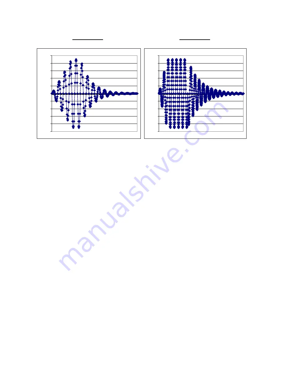
Figure 5-3A
Figure 5-3B
-100
-80
-60
-40
-20
0
20
40
60
80
100
-100
-80
-60
-40
-20
0
20
40
60
80
100
Note: The scales of the “X” axes are not the same.
5.2.3.3 Receive Signal Select, Gain, Digitization, Integration and Storage
When the FPGA determines it is time to read the receive signal from a particular
transducer/preamp it sends the appropriate channel select code to the four channel
multiplexer. The multiplexer then places the desired analog receive signal on the
input of the “A” half of a dual DAC. The DAC applies the appropriate gain that
is determined by the FPGA to this signal and places the result on the input of a
twelve bit Analog to Digital converter (ADC). The ADC begins doing a
conversion when it receives a start signal from the FPGA. Each conversion takes
0.5
µsec. At the end of each conversion the digital value is passed to the FPGA
where it is filtered, rectified, and added to the appropriate boxcar in the RAM.
Another start signal is then issued and the ADC starts another conversion cycle.
This continues for 32,384 cycles creating a sixteen millisecond wide window of
0.5
µ
sec filtered digital averages. The RAM has a separate boxcar window for
each transducer. After the digitized window is complete the FPGA channel select
requests a different transducer/preamp signal from the multiplexer and the ADC
conversions begin forming the digital, (boxcar) window for that transducer. The
channel select continues cycling through the transducers and adding conversions
to the boxcars in the window until the desired integration time is over. This is
typically 30 seconds. At the end of the integration period the FPGA sends a
“Measurement Complete” signal to the 332 Processor. The 332 Board issues a
“Wait” signal to the FPGA, while it reads the four windows of “Boxcar” data, and
processes the data into time measurements and velocity readings. Then it begins
the next sampling cycle for the duration of the integration period.
E S Transducer Drive (50 KHZ)
LR003 Transducer Drive (20
5-5
Summary of Contents for ULTRAFLOW 150
Page 2: ...DOCUMENT NO 1900 0100 01 REV E ...
Page 24: ...ULTRAFLOW 150 GAS FLOW AND TEMPERATURE MONITOR This page intentionally left blank 4 6 ...
Page 75: ...SECTION 7 0 INSTALLATION This page intentionally left blank 7 7 ...
Page 76: ......
Page 85: ...SECTION 8 0 SYSTEM CALIBRATION AND ADJUSTMENT This page intentionally left blank 8 9 ...
Page 86: ......
Page 89: ...APPENDIX A SITE SPECIFICATION DATA SHEETS ...
Page 90: ...ULTRAFLOW 150 GAS FLOW AND TEMPERATURE MONITOR This page intentionally left blank ...
Page 95: ...APPENDIX B MAINTENANCE CHECK SHEETS ...
Page 96: ... This page intentionally left blank ...
Page 101: ...APPENDIX C SPARE PARTS ...
Page 102: ... This page intentionally left blank ...
Page 105: ......
Page 106: ...APPENDIX D DRAWINGS ...
Page 107: ... This page intentionally left blank ...
Page 108: ......
Page 109: ......
Page 110: ......
Page 111: ......
Page 112: ......
Page 113: ......
Page 114: ......
Page 115: ......
Page 116: ......
Page 117: ......
Page 118: ......
Page 119: ......
Page 120: ......
Page 121: ......
Page 122: ......
Page 123: ......
Page 124: ......
Page 125: ......
Page 126: ......
Page 127: ......
Page 128: ......
Page 129: ......
Page 130: ......
Page 131: ......
Page 132: ......
Page 133: ......
Page 134: ......
Page 135: ......
Page 136: ......
Page 137: ......
Page 138: ......
Page 139: ......
Page 140: ......
Page 141: ......
Page 142: ......
Page 143: ......
Page 144: ...APPENDIX E ENHANCED SERIAL PORT COMMUNICATION PROTOCOL ...