background image

24

www.teejet.com

Aeros 9040 field computer

HOME

GUID

ANCE

FULL SCREEN

IMPLEMENT

INTR

ODUC

TION

GNSS

RA

TE C
ONTR

OL

APPENDIX

SE

TUP

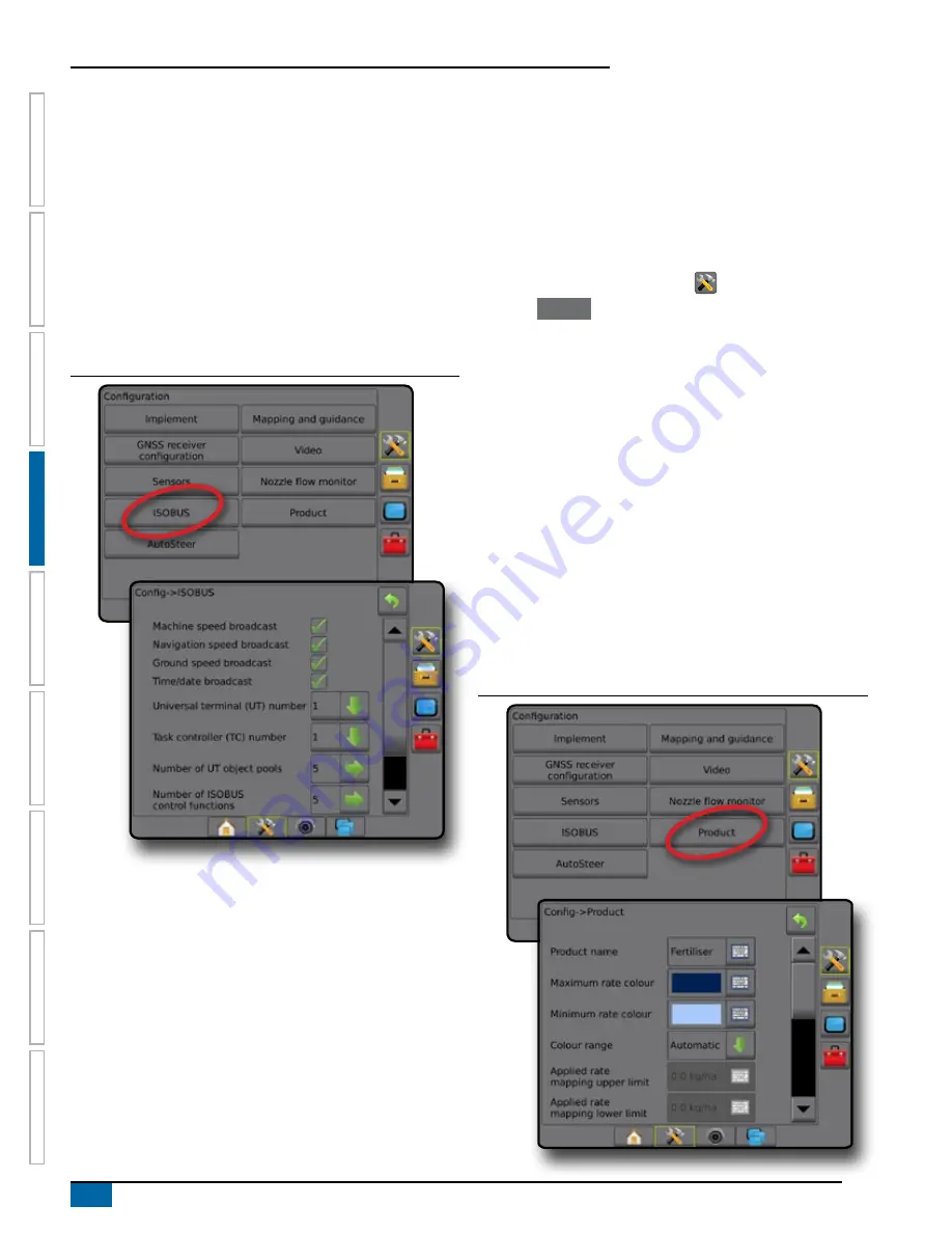
The following items on the ISOBUS page are for use 

only

 by TeeJet 

support technicians. 

►Universal terminal (UT) Number [support technicians only] – 

used to define the unique number for this specific UT

►Task controller (TC) Number [support technicians only] – used 

to define the unique number for this specific TC

►Number of UT object pools [support technicians only] – shows 

the number of UT object pools are currently stored in the 

console

►Number of ISOBUS control functions [support technicians 

only] – shows the number of ISOBUS control functions 

communicating on the ISOBUS

Figure 4-24: ISOBUS options

Product

When an ISOBUS rate control system is present, Product options 

are available for configuring product control channel names, product 

volumes, application rates, increment for adjusting rates, and 

maximum/minimum rate limits and corresponding display colours for 

mapping.

NOTE:  For more information, see the Rate control chapter of this 

manual.

1.  Press CONFIGURATION side tab 

.

2.  Press 


Product


.

3.  Select from:

►Product name – used to enter the name of the product for the 

current Control Channel

►Maximum/minimum rate colour – used to create the colour 

scheme that best represents the change in rates across an 

application or target rate map

►Color range – used to select automatic or manual mode for 

setting maximum and minimum rate colour

►Applied rate mapping upper limit [Manual colour range 

only] – used to set the maximum rate for which the Maximum 

rate colour will used (higher rates will use the selected 

Maximum rate colour)

►Applied rate mapping lower limit [Manual colour range 

only] – used to set the minimum rate for which the Minimum 

rate colour will used (lower rates will use the selected 

Minimum rate colour)

Figure 4-25: Product options

Summary of Contents for AEROS 9040

Page 1: ...Software version 4 31 U S E R M A N U A L AEROS 9040...

Page 2: ...INTERRUPTION OF BUSINESS OR FOR INDIRECT SPECIAL INCIDENTAL OR CONSEQUENTIAL DAMAGES OF ANY KIND EVEN IF TEEJET TECHNOLOGIES HAS BEEN ADVISED OF SUCH DAMAGES ARISING FROM TEEJET TECHNOLOGIES SOFTWARE...

Page 3: ...3 Unavailable options when job is active 3 Console screen colours 4 Simple or advanced mode 4 Warnings and information pop ups 5 Setup option information 5 Drop down menu selections 5 Scrolling screen...

Page 4: ...ole only 17 Mapping and guidance using an external lightbar 18 User entered mapping location 19 GNSS 20 Video 21 Sensors 21 Input output module pressure sensor 22 Nozzle flow monitor 23 ISOBUS 23 Prod...

Page 5: ...ections with ISOBUS sprayer setup 50 Spreader TeeJet 51 Single section 51 Multiple sections 52 Spreader OEM 54 Single section 54 Multiple sections 54 Staggered 55 Multiple sections 55 APPLICATION OR W...

Page 6: ...4 Navigation activity Boom status 74 Selectable Information 74 STATUS BAR 75 Status information screens 76 NAVIGATION SCREENS 78 Vehicle view 78 Field view 79 RealView guidance 80 GUIDANCE MODES 81 St...

Page 7: ...92 Boundaries 92 Establishing an exterior or interior boundary 92 Delete last marked boundary 94 Boundary on status bar 94 Polygons 94 Establishing a polygon 94 Delete last marked polygon 95 MAPPING O...

Page 8: ...ns 104 MAPPING OPTIONS 104 Coverage map 105 Polygons map 105 Prescription map 106 Application and target rate maps 106 Application map 106 Target rate map 107 Colour range selection 107 APPENDIX A SYS...

Page 9: ...up to 8 cameras External GNSS receiver or antenna upgrades Fieldware Link enhanced data organization application Pressure sensor interface kit for droplet size monitor ISOBUS rate control Reverse sens...

Page 10: ...econds before restarting the console RealView camera The TeeJet Technologies RealView camera allows video images to be displayed on the Aeros screen The camera can be pointed forward to enable RealVie...

Page 11: ...drop down menus or keyboard entry screens To quickly find a setup feature see Aeros console menu settings in this manual Bottom tab keys The bottom tab keys are always available on screen These keys g...

Page 12: ...ome screen Only the current job is available for saving in Reports Use with Fieldware Link is not available Figure 1 6 Simple mode home screen In advanced mode more than one job will be available at a...

Page 13: ...the information box press anywhere on the screen Figure 1 9 Example of information text box Drop down menu selections Press DOWN arrow to access the options Use the UP DOWN arrows or slide bar if nec...

Page 14: ...er a value Press the ACCEPT icon to save the settings or the CANCEL icon to leave the keypad without saving Figure 1 12 Example of keyboard GNSS antenna height m 1 2 3 3 50 Clear 4 5 6 7 8 9 0 Next pa...

Page 15: ...unded area coverage areas and application time are displayed on the home screen Only the current job is available for saving in Reports Use with Fieldware Link is not available Figure 2 1 Simple mode...

Page 16: ...le must have GNSS before starting or continuing a job New job Starting a new job will clear the previous job data To start a new job 1 On the Home screen press New job 2 Press Yes to automatically gen...

Page 17: ...f the video input Split camera view one of two sets of four camera inputs A B C D or E F G H can be selected to divide the screen into four separate video feeds To adjust the camera view reverse upsid...

Page 18: ...iew camera full screen video view VSM camera options If a Video selection module VSM is installed on the system two 2 video options are available 1 Press REALVIEW CAMERA FULL SCREEN VIDEO VIEW bottom...

Page 19: ...htbar GNSS receiver configuration Video configuration Sensors Input output module IOM pressure sensor Nozzle flow monitor ISOBUS configuration Product configuration AutoSteer FieldPilot valve setup st...

Page 20: ...n 1 offset direction distance overlap percentage delay on off times section offsets Mapping and guidance used to configure the mapping location guidance width guidance sensitivity cross track error an...

Page 21: ...ation section or sections have no length and can be at different distances from the line availability depends on the specific equipment in the system NOTE For more information see Implement type in th...

Page 22: ...NSS antenna height when available used to measure the height of the antenna from the ground Implement type used to select the layout of the sections for the applied product location Application width...

Page 23: ...om the ground Implement type used to select the layout of the sections for the applied product location Symmetric implement used to establish if sections are paired and therefore share the same width...

Page 24: ...d press Accept 4 Press RETURN arrow or CONFIGURATION side tab to return to the main Configuration screen Figure 4 9 Droplet size monitor Nozzle selection Nozzle selection enables up to five 5 tips to...

Page 25: ...dule ELM Mapping and guidance console only used to configure the mapping location guidance width and guidance sensitivity cross track error shown on the on screen guidance bar Mapping and guidance usi...

Page 26: ...represents the vehicle When set to vehicle the center LED represents vehicle location and the moving LED represents the guideline LED spacing When External lightbar is enabled sets the distance away...

Page 27: ...n line offset direction used to select whether the mapping location is located in front of or behind the GNSS antenna as the vehicle moves in a forward direction Mapping location in line offset distan...

Page 28: ...am only TeeJet support technicians should use this feature PRN selects the first of two possible SBAS PRN s to provide SBAS correction data Set to Automatic for automatic PRN selection Alternate PRN w...

Page 29: ...ress RETURN arrow or CONFIGURATION side tab to return to the main Configuration screen Figure 4 17 Video with 4 channel VSM options Video setup unavailable If a camera or VSM is not connected setup op...

Page 30: ...commended by the manufacturer Low pressure alarm used to enter the user determined low pressure point at which the alarm will sound High pressure alarm used to enter the user determined high pressure...

Page 31: ...ozzle balance process Nozzle flow monitor balance used to start the nozzle flow balance process 4 Press RETURN arrow or CONFIGURATION side tab to return to the main Configuration screen Figure 4 22 No...

Page 32: ...control channel names product volumes application rates increment for adjusting rates and maximum minimum rate limits and corresponding display colours for mapping NOTE For more information see the Ra...

Page 33: ...y Valve diagnostics used to test the valves to see if they are connected properly Options Steering wheel sensor used to select whether the steering disengage sensor is magnetic or pressure sensor base...

Page 34: ...sition based on the satellite geometry that is used to calculate it A value of 1 to 2 is excellent 2 5 is good 5 10 is moderate 10 20 is fair and anything over 20 is poor Assisted automatic steering s...

Page 35: ...5 Press RETURN arrow or CONFIGURATION side tab to return to the main Configuration screen NOTE If FieldPilot or UniPilot is being used a Tilt gyro module is built into the system When using a FieldPil...

Page 36: ...selected file or load the selected file s machine setting Figure 4 29 Data management options Job data When in advanced job mode job data options are used to transfer job information delete import exp...

Page 37: ...orage to internal storage Delete Job data used to delete job data from internal storage 5 Press RETURN arrow or DATA MANAGEMENT side tab to return to the main Data management screen Figure 4 31 Job da...

Page 38: ...job s guidelines boundaries applied data prescription map and or polygons to be copied into a new job 7 Press Copy 8 Name the new job 9 Press the ACCEPT icon to save the new job or the CANCEL icon to...

Page 39: ...job to enable the function When closing a job with a USB drive in the console you get the option to create a report on the current job 1 Press DATA MANAGEMENT side tab 2 Press Reports 3 Insert a USB d...

Page 40: ...than one job will be available at any time Client farm field and job names bounded and coverage areas application time and distance from selected job are displayed on the home screen All saved job pro...

Page 41: ...e settings the saving of the current machine settings to the selected machine settings or the loading of the selected machine settings to the current settings 4 Press RETURN arrow or DATA MANAGEMENT s...

Page 42: ...om internal storage Save used to save the current machine settings to the selected machine settings Load used to load the selected machine settings to the current settings 5 Press RETURN arrow or DATA...

Page 43: ...speaker Demo GNSS used to start playback of simulated GNSS data Feature Unlock used to unlock advanced features Figure 4 41 Console options About About Save screen displays the system software versio...

Page 44: ...saved to a USB drive Screen calibration used to calibrate the touch screen 4 Press RETURN arrow or CONSOLE side tab to return to the main Console settings screen Figure 4 43 Display options Cultural C...

Page 45: ...de tab to return to the main Console settings screen Figure 4 45 Audio volume options Demo GNSS Demo GNSS is used to start the playback of a simulated GNSS signal WARNING This tool will disable incomi...

Page 46: ...ct TeeJet Technologies customer service Once unlocked a feature remains unlocked unless the console is fully reset 1 Press CONSOLE side tab 2 Press Feature unlock 3 Press the locked feature button for...

Page 47: ...r and Units converter Figure 4 49 Tools options Upload software The Upload software screen is used to upload software updates from a USB drive for system devices 1 Press TOOLS side tab 2 Press Upload...

Page 48: ...s 1 Press TOOLS side tab 2 Press Extras 3 Select from Calculator used to perform mathematical calculations Units converter used to perform unit conversions for area length volume pressure mass tempera...

Page 49: ...ternal or External GNSS status information displays current baud rate baud rate status GNSS status information GGA VTG data rates number of satellites HDOP PRN GGA quality receiver receiver version UT...

Page 50: ...A QI of 1 or 2 3 4 or 5 are also accepted GPS GLONASS SBAS either single point uncorrected or SBAS corrected position data are accepted GGA QI of 1 or 2 3 4 or 5 are also accepted GPS GLONASS SBAS DGP...

Page 51: ...ond Number of satellites the number of GNSS satellites in view minimum of 4 are required for DGPS HDOP a measure of satellite geometry strength in the horizontal plane A HDOP value of less than 2 is p...

Page 52: ...st programming as required Figure 5 6 Programming receiver PRN The PRN menu allows selection of up to two specific SBAS satellites to use for SBAS corrections This allows the user to remove SBAS corre...

Page 53: ...Network RTK A series of base stations spread across a given geographic region such as an entire state county that are networked via a centralized computer and which broadcast RTK correction data over...

Page 54: ...ication that makes the RTCM correction data from the CORS stations available to anyone with an internet connection and the appropriate log on credentials to the NTRIP server Typically uses a cellular...

Page 55: ...ystem Multiple section output modules Multiple section output modules may be installed on the CAN bus to allow more sections than a single module allows If a section control module is on the system th...

Page 56: ...Sections are numbered from left to right while facing in the machine s forward direction Straight The boom sections have no length and are on a line a fixed distance from the antenna Single section N...

Page 57: ...to the centre of the implement while facing in the machine s forward direction Implement lateral offset distance defines the lateral distance from the centreline of the machine to the centre of the im...

Page 58: ...ne of the machine displays the in line distance from the GNSS antenna to the implement Implement lateral offset direction displays the lateral direction either left or right from the centreline of the...

Page 59: ...er type Antenna to disks in line offset distance measured in parallel to the centreline of the machine defines the in line distance from the GNSS antenna to the disks or dispersal mechanism Implement...

Page 60: ...he centre of the implement Overlap used to define the amount of overlap allowed when using automatic boom section control Delay on time used to set the time when the section will switch on when enteri...

Page 61: ...MPLEMENT Figure 6 17 Multiple sections Figure 6 18 Distances and length Figure 6 19 Lateral offset direction and distance Centre of the GNSS antenna Antenna to disks in line offset distance Implement...

Page 62: ...TE Consult spreader manufacturer for start and stop distances 4 Press RETURN arrow to return to the Implement screen or CONFIGURATION side tab to return to the main Configuration screen Figure 6 21 Si...

Page 63: ...he zero point of the Section Offsets Sections are numbered from left to right while facing in the machine s forward direction Implement lateral offset direction defines the lateral direction either le...

Page 64: ...nd distances behind section 1 Centre of the GNSS antenna Section 1 in line offset direction distance Implement lateral offset direction distance Section offsets Figure 6 25 Offset directions and dista...

Page 65: ...control is available when any of the following are on the system SmartCable Section driver module SDM Switch function module SFM or compatible ISOBUS Implement ECU Application width or Working width i...

Page 66: ...Self propelled front mount Centre of the GNSS antenna Centre of the rear axle Connection point in line offset direction distance Connection point lateral offset direction distance not illustrated B S...

Page 67: ...plement Aeros settings 1 Press SYSTEM SETUP bottom tab 2 Press CONFIGURATION side tab 3 Press Implement 4 Select Implement type Straight 5 Press Implement type NEXT PAGE arrow to set up specific imple...

Page 68: ...s Connection point in line offset direction Implement in line offset distance calculated based on Aeros Connection point in line offset distance and ISOBUS Sprayer B Section X offset entries Implement...

Page 69: ...values for Connector type Trailed A Connection X offset measured in parallel to the centreline of the machine define the distance from point to the center of the front axle of trailed implement B Sect...

Page 70: ...Implement lateral offset distance GNSS offset adjustment calculation To calculate a GNSS offset adjustment using the same guideline 1 Create a straight AB line 2 With assisted auto steering engaged d...

Page 71: ...he difference between the flags of pass and pass 5 Divide the measured distance in half This difference will be the offset adjustment 6 Increase or decrease the offset distance as needed dependent on...

Page 72: ...t in reverse active allows for product application automatic section control and mapping that is correct for reverse machine movement Speed on the Guidance bar will turn red while traveling in reverse...

Page 73: ...eset 1 5 selects up to five 5 tips for quick recall and selected the current nozzle for determining droplet size information Current nozzle displays the current nozzle 5 Press RETURN arrow or CONFIGUR...

Page 74: ...d disabled The DSM then becomes available on the operation screens Setup Enable disable DSM 1 Press CONFIGURATION side tab 2 Press Implement 3 Press Droplet size monitor 4 Select if droplet size monit...

Page 75: ...he eight droplet size classification categories always remember that a single nozzle can produce different droplet size classifications at different pressures A nozzle might produce medium droplets at...

Page 76: ...ation and guidance options on the guidance screens BoomPilot icon used to establish if the BoomPilot icon is available in the navigation and guidance options on the guidance screens for manually contr...

Page 77: ...irect product application Overview Three guidance screens assist in keeping you informed Vehicle view guidance creates a computer generated image of the vehicle position displayed in the application a...

Page 78: ...ield View 12 deg 13 0 0 Vehicle View 12 deg 13 0 0 3 5 bar Navigation and guidance options On any guidance screen displays navigation options including guidance modes guideline options return to point...

Page 79: ...ault reset Clears any nozzle fault indications Refresh GNSS position Resets the ClearPath filter in the OEMStar receiver Boundary and polygon options On any guidance screen displays exterior boundary...

Page 80: ...e controller is on the system or a polygon has been established 12 deg 13 0 0 3 5 bar Coverage map shows areas covered by the implement regardless of whether product was applied Polygon map shows all...

Page 81: ...ew guidance screen displays camera setup and guidance over video options 12 deg 13 0 0 Video camera select selects one of up to eight camera views if a Video selection module VSM is attached Split cam...

Page 82: ...East 90 South 180 West 270 Total applied area displays the total accumulated area that has had product applied including double coverage areas Application time displays the total time application is a...

Page 83: ...side exterior boundary traveling inside exterior bounded area No icon no boundary established exterior or interior Assisted auto steering status Green engaged actively steering Yellow enabled all cond...

Page 84: ...Figure 7 7 Guidance mode status 27 00 ha 10 0 km h Mark A Guidance pattern Straight AB Guidance Guideline name Stream Edge Total number of guidelines 4 Bounded area status Bounded area status displays...

Page 85: ...STATUS icon Figure 7 11 BoomPilot status 27 00 ha 10 0 km h Mark A Number of sections 15 Droplet pressure status Droplet pressure status displays information regarding the current status of the dropl...

Page 86: ...tion of active boom sections Navigation and guidance options tab Boundary and polygon options tab Mapping options tab Application control options tab Current pressure On screen guidance Guidelines Ora...

Page 87: ...rlap coverage area Status bar Boundary and polygon options tab Screen options tab Guidance bar Mapped coverage area Navigation guidelines Vehicle representation Navigation and guidance options tab On...

Page 88: ...stem two 2 video options are available One camera view one of up to eight camera inputs can be selected to change the view of the video input Split camera view one of two sets of four camera inputs A...

Page 89: ...idance Adaptive curve AB guidance Adaptive curve guidance provides guidance along a curved line based on an initial AB reference line where each adjacent guideline is drawn from the projected guidance...

Page 90: ...de to another will change the current available guidelines Multiple guidelines can be created in each guidance mode If more than one guideline is saved in a single guidance mode the Next Guideline fea...

Page 91: ...er name 1 5 9 2 6 0 3 7 4 8 q Caps Alt t f v o k Shift w a z y g b p l e s x u h n r d c i j m Figure 7 20 Follow guidance 13 18 7 2 km h 0 0 A nudge feature The A nudge feature allows the current gui...

Page 92: ...AVIGATION AND GUIDANCE OPTIONS tab to display navigation options 2 Press NEXT GUIDELINE icon Toggle between all guidelines by pressing the NEXT GUIDELINE icon again Figure 7 22 Next guideline 13 7 2 k...

Page 93: ...ll be provided for the next adjacent row When the vehicle is in the row the guideline is removed 5 Repeat at the end of the next row NOTE The NextRow guidance feature does not support skipping rows Fi...

Page 94: ...NT icon Figure 7 28 Return point established Vehicle view 8 19 1 7 km h 8 21 1 7 km h Delete the return point To delete the established return point 1 Press NAVIGATION AND GUIDANCE OPTIONS tab to disp...

Page 95: ...m h 0 00 ha Mark A No Section control module If a section control system is not present the BoomPilot icon or an optional work on off switch is used to turn the single section on or off Only one secti...

Page 96: ...ANCE OPTIONS tab to display navigation options 2 Press BOOMPILOT icon Automatic status bar icon will change to red 3 Press ISOBUS UNIVERSAL TERMINAL bottom tab 4 Go to the Operation screen 5 Use the S...

Page 97: ...g BoomPilot Regulation mode should be Manual To set configuration settings 1 Press SYSTEM SETUP bottom tab 2 Press CONFIGURATION side tab 3 Press Implement 4 Set BoomPilot icon to Enable NOTE BoomPilo...

Page 98: ...e SFM is present BoomPilot is used to set automatic section control to off manual automatic or spot application NOTE The BOOMPILOT icon is grey when GNSS is unavailable BoomPilot status bar icon will...

Page 99: ...GNSS data This will most likely result in sections already on in automatic BoomPilot mode to go off for a short period of time The refresh should not be done during active application To refresh the...

Page 100: ...ntrol can then be used NOTE If a boundary is mapped with some sections folded as described above it may be necessary to use the A NUDGE icon on the guideline over to the correct position for subsequen...

Page 101: ...n Continue using this location Yes Cancel 2 32 ha 7 2 km h 3 68 ha 7 2 km h 3 68 ha 7 2 km h Area bounded 64 45 ha Would you like to save the marked boundary Save Delete Figure 7 36 Add interior bound...

Page 102: ...be stored within a single job Application is not required to map a polygon Using Data Job data Manage or with Fieldware Link a user can duplicate and edit jobs for reuse of polygons for different app...

Page 103: ...save and name the marked polygon Save without naming Save and name Discard 7 03 ha 7 2 km h Polygon name 1 5 9 2 6 0 3 7 4 8 q Caps Alt t f v o k Shift w a z y g b p l e s x u h n r d c i j m 7 03 ha...

Page 104: ...for use in applying product Application map shows how much product has been applied and where using colour to indicate level in proportion to preset or automatically set maximum and minimum levels Ta...

Page 105: ...the ISOBUS Sprayer application options 1 Press APPLICATION CONTROL OPTIONS tab to display application control options 2 Select from Target rate percentage increase establishes the required boost perce...

Page 106: ...ing angle indicator Single camera a single camera is directly attached to the console Video selection module if a Video selection module VSM is installed on the system two 2 video options are availabl...

Page 107: ...on line up or down Figure 7 47 RealView setup options 0 0 km h 0 00 ha 0 0 0 0 km h 0 00 ha 0 0 0 0 km h 0 00 ha 0 0 Camera snapshot RealView Camera Snapshot saves a still photo of the current view on...

Page 108: ...ME SETUP FULL SCREEN IMPLEMENT INTRODUCTION GNSS RATE CONTROL APPENDIX GUIDANCE Figure 7 49 Single camera selection with VSM 0 0 km h 0 00 ha 0 0 0 0 km h 0 00 ha 0 0 Figure 7 50 Select split view wit...

Page 109: ...avigation menu and data rich display Provides basic or variable rate control Add additional ISOBUS ECUs as your needs change NOTE For detailed setup instructions refer to the specific ISOBUS user manu...

Page 110: ...ion provided by the machine over the ISOBUS Ground speed broadcast used to establish if the GNSS speed shall be broadcast as Ground based speed on the ISOBUS from this console Time date broadcast used...

Page 111: ...e nozzle NOTE The current pressure is also available on the ISOBUS Operation screen Figure 8 6 Guidance screen options 10 0 km h 3 5 bar 27 00 ha Mark A Application control options On vehicle view gui...

Page 112: ...displays options to display polygon maps coverage maps and application maps Polygon and coverage mapping are available when a polygon has been established GNSS based product application mapping is av...

Page 113: ...indicate level in proportion to preset or automatically set maximum and minimum levels Target rate map shows the application rate that the rate controller attempted to achieve at each location NOTE Ap...

Page 114: ...uded maps to create Target rate or Prescription maps and transfer back to the console for job use NOTE Advanced job mode is required for variable rate applications See Options Job mode in the System s...

Page 115: ...een on the UT Boosting can also be controlled using the Vehicle view screen Up to five 5 target rates can be established Colour range selection Product options configure maximum minimum rate limits an...

Page 116: ......

Page 117: ...ly OR 45 09031 Aeros Junction Box COBO IBBC 45 09026 IC18 to ISOBUS Hitch Harness 45 10128 IC18 to Sensors Valves Harness IC18 Sprayer IC18 Sprayer Switch Box Extension Cable 45 09023 20 ft 6 m 45 090...

Page 118: ...65 05246 UniPilot Pro Anti Rotation Bracket Kit Generic 45 05986 Ethernet Interface RJ5 to Conxall 32 04020 Foot Switch 45 10166 UniPilot Pro Harness 91 05023 UniPilot Pro Electric Steering Device 65...

Page 119: ...031 Aeros Junction Box COBO IBBC Extension Cable 45 09023 20 ft 6 m 45 09024 30 ft 9 m 45 09025 40 ft 12 m to Ground Speed to Spinner RPM Sensor to Remote Spread Switch to Dump Valve 45 20006 Power Ca...

Page 120: ...ware Link with profile Configuration settings Configuration settings Available with active job Can be edited in Saved to exported profile in Aeros 9040 Fieldware Link Aeros 9040 Fieldware Link Impleme...

Page 121: ...t lateral offset direction Implement lateral offset distance Overlap Delay on off times Section offsets Mapping and guidance Mapping location Location name Mapping location in line offset direction Ma...

Page 122: ...limit AutoSteer with FieldPilot Pro or UniPilot Pro Manage vehicles New Load Edit Copy Auto calibration Adjust Delete Adjust Manual disengage Motor aggressiveness UniPilot Pro freeplay Steering respon...

Page 123: ...ptions Job Mode Machine settings Transfer Export Import Delete Manage New Copy Delete Save Load Console settings Console settings Available with active job About System information Save Display Colour...

Page 124: ...nnectors Power CAN 35 pin AMPseal Camera 5 pin Conxall Environmental Storage 10 C to 70 C Operating 0 C to 50 C Humidity 90 non condensing Display 800 x 600 resolution 8 4 in 21 3 cm Input Output CAN...

Page 125: ...atitude zones designated by letters as shown below Figure A 5 UTM coordinate system Global The Aeros console then tracks the UTM zones in which each product application job is performed The UTM zone i...

Page 126: ...Auto Steering UniPilot Pro Assisted Steering BoomPilot Automated Boom Section Control Tilt Gyro Module Video Selection Modules for up to 8 Cameras External GNSS Receiver Or Antenna Upgrades Fieldware...

Reviews: