Disabled Passenger Lift DPT-512 | 14
SECTION 1 | GENERAL INFORMATION & OPERATING PROCEDURES
The truck includes the following features:
Hydraulic pump and PTO- mounted on transmission. This unit is driven by
the transmission through a hydraulically engaged clutch mounted directly
to the hydraulic pump. It runs on demand whenever the engine is running,
the PTO switch is ON, and a stabilizer up or down or body up control
switch is engaged.
Warning alarm – sounds whenever the vehicle is being driven in reverse,
the lift is being lowered, or the stabilizers are being lowered.
Truck electrical system – provides electrical power for all functions.
Additional regulatory switches and electrical components added to the
engine compartment are defined in the electrical system description.
1.1.2 | Hydraulic Stabilizers
The stabilizers are hydraulically actuated legs that extend to the ground on
both sides of the vehicle. The four stabilizers provide stability while the van
body is extended upward.
1.1.3 | Body Lift Mechanism
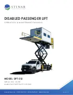
The van body is mounted on a double scissors lift mechanism, enabling
the body to be raised vertically while the van body floor remains parallel to
the ground. The double scissors design is constructed of 8” x 3” (203 mm
x 76 mm) reinforced steel tubing. All pivot points are provided with grease
fittings. The scissors mechanism is raised by two hydraulic lift cylinders. A
solenoid-actuated control valve located on the truck chassis regulates the
flow of hydraulic fluid to the cylinders. This control valve is activated by
electrical switches in the cab or in the van body.
• The scissors lift mechanism consists of a lower sub-frame and track,
attached to the chassis; an upper sub-frame and track, attached to
the van body, and inner and outer double scissors. The scissors are
secured to the two sub-frames at the front of the lift mechanism.
Rollers on the rear of the scissors travel in the sub-frame channels
as the scissors are raised and lowered.
• Two hydraulic cylinders raise and lower the scissors. Each of these
telescopic cylinders is fitted with an electrically released lock valve
to prevent undesired downward movement. A flow control valve
controls the rate of descent of the cylinders.
• Scissors are supplied with maintenance stops to hold the scissors in
elevated positions for routine maintenance. These are described in
Chapter 2, Servicing.
Summary of Contents for 25781
Page 12: ...Disabled Passenger Lift DPT 512 12 FIGURE 1 1 1 DISABLED PASSENGER TRANSPORTER MODEL DPT 512...
Page 13: ...Disabled Passenger Lift DPT 512 13 FIGURE 1 1 1 DISABLED PASSENGER TRANSPORTER MODEL DPT 512...
Page 22: ...Disabled Passenger Lift DPT 512 22 FIGURE 1 1 10 HYDRAULIC COMPONENT GROUP...
Page 33: ...Disabled Passenger Lift DPT 512 33 FIGURE 1 2 1 1 CAB CONTROLS AND INDICATORS...
Page 36: ...Disabled Passenger Lift DPT 512 36 FIGURE 1 2 1 3 VAN BODY CONTROL STATION...
Page 38: ...Disabled Passenger Lift DPT 512 38 FIGURE 1 2 1 7 EMERGENCY OPERATING CONTROLS...
Page 57: ...Disabled Passenger Lift DPT 512 57 FIGURE 2 1 9 3 LUBRICATION POINTS...
Page 74: ...Disabled Passenger Lift DPT 512 74 FIGURE 2 3 1 HYDRAULIC COMPONENT GROUP...
Page 95: ...Disabled Passenger Lift DPT 512 95 FIGURE 4 2 5 PLATFORM ASSEMBLY 6 7 8 4X 2 3 8X 1 5 4 9...
Page 107: ...Disabled Passenger Lift DPT 512 107 FIGURE 4 2 11 CAB CONTROLS AND INDICATORS...
Page 109: ...Disabled Passenger Lift DPT 512 109 FIGURE 4 2 12 VAN BODY CONTROL STATION...
Page 111: ...Disabled Passenger Lift DPT 512 111 FIGURE 4 2 13 REAR VAN CONTROL STATION...


