Disabled Passenger Lift DPT-512 | 11
SECTION 1 | GENERAL INFORMATION & OPERATING PROCEDURES
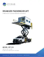
The Stinar Disabled Passenger Transporter Model DPT-512, is a truck
mounted aircraft service vehicle designed for transporting injured or
disabled personnel to and from aircraft.
The vehicle consists of a truck chassis cab equipped with a hydraulic scissors
lift mechanism capable of elevating the van body to aircraft door threshold
heights of 90 to 228 inches (2286 to 5791 mm). A hydraulic rear lift gate
transfers passengers between ground level and the van body.
The van body has a rated capacity of 3000 pounds (1361 kg). Hydraulically
operated stabilizers are provided for stabilizing the vehicle whenever the
van body is raised.
The scissors lift and the stabilizers are powered by a hydraulic pump driven
from the trucks transmission. The hydraulic pump functions only when the
PTO is turned on from the cab control station. The van lights, the controls,
and the linear actuator on the front platform are all run off the truck’s 12
VDC electrical system. A hand hydraulic pump provides hydraulic power for
emergency use.
The unit is designed to transport personnel on airport ramp areas, service
roads, and public highways.
1.1.1 | Equipment Systems and
Components
The major operating systems and components of the Disabled Passenger
Transporter are described in the paragraphs below. See Figure 1.1.1 for the
locations of components.
1.1.1.1 | Truck Chassis-cab
The Disabled Passenger Transporter is built on a Ford F-550, 4 x 2 chassis
cab and is powered by a 6.8 liter, V-10 gas engine. The transmission is a
5-speed automatic. The chassis is equipped with dual rear wheels.
Controls and indicators added to the cab include:
• Van body raise/lower controls
• Stabilizer raise/lower controls
•
Flashing beacon on/off switch
•
PTO on/off switch
•
Front/rear on/off floodlights
•
Van body lighting on/off controls
1.1 | DESCRIPTION
Summary of Contents for 25781
Page 12: ...Disabled Passenger Lift DPT 512 12 FIGURE 1 1 1 DISABLED PASSENGER TRANSPORTER MODEL DPT 512...
Page 13: ...Disabled Passenger Lift DPT 512 13 FIGURE 1 1 1 DISABLED PASSENGER TRANSPORTER MODEL DPT 512...
Page 22: ...Disabled Passenger Lift DPT 512 22 FIGURE 1 1 10 HYDRAULIC COMPONENT GROUP...
Page 33: ...Disabled Passenger Lift DPT 512 33 FIGURE 1 2 1 1 CAB CONTROLS AND INDICATORS...
Page 36: ...Disabled Passenger Lift DPT 512 36 FIGURE 1 2 1 3 VAN BODY CONTROL STATION...
Page 38: ...Disabled Passenger Lift DPT 512 38 FIGURE 1 2 1 7 EMERGENCY OPERATING CONTROLS...
Page 57: ...Disabled Passenger Lift DPT 512 57 FIGURE 2 1 9 3 LUBRICATION POINTS...
Page 74: ...Disabled Passenger Lift DPT 512 74 FIGURE 2 3 1 HYDRAULIC COMPONENT GROUP...
Page 95: ...Disabled Passenger Lift DPT 512 95 FIGURE 4 2 5 PLATFORM ASSEMBLY 6 7 8 4X 2 3 8X 1 5 4 9...
Page 107: ...Disabled Passenger Lift DPT 512 107 FIGURE 4 2 11 CAB CONTROLS AND INDICATORS...
Page 109: ...Disabled Passenger Lift DPT 512 109 FIGURE 4 2 12 VAN BODY CONTROL STATION...
Page 111: ...Disabled Passenger Lift DPT 512 111 FIGURE 4 2 13 REAR VAN CONTROL STATION...


