39
6.5
Voltage Protection Control
This control protects the units from abnormally high or abnormally low voltages.
When the phase voltage of AC power supply is at or above 265V for more than 30 seconds, the system displays H5 protection
and all the units stop running. When the phase voltage drops below 250V for more than 30 seconds, the unit restart once the
compressor re-start delay has elapsed. When the phase voltage is below 170V for more than 30 seconds, the system displays H5
protection and all the units stop running. When the AC voltage rises to at or above 180V for more than 30 seconds, the
refrigerant system restarts once the compressor re-start delay has elapsed.
6.6
DC Fan Motor Protection Control
This control protects the DC fan motors from abnormal power supply. DC fan motor protection occurs when the fan module does
not receive any feedback from the fan motor.
When DC fan motor protection control occurs the system displays the PU error code and the unit stops running. When PU
protection occurs 10 times in 120 minutes, the FF error is displayed. When an FF error occurs, a manual system restart is
required before the system can resume operation.
6.7
Water Side Heat Exchanger Anti-freeze Protection Control
When water side heat exchanger anti-freeze protection occurs the system displays error code Pb and all the units stop running.
6.8
Air Side Heat Exchanger High Temperature Protection Control
This control protects the air side heat exchanger from high temperature.
Note:
1. T3: Air side heat exchanger refrigerant outlet temperature
When the air side heat exchanger refrigerant outlet temperature (T3) rises above 62°C, the system displays P7 protection and all
the units stop running. When the air side heat exchanger refrigerant outlet temperature (T3) drops below 55°C, the compressor
enters re-start control.
Voltage ≥ 265V
or Voltage ≤ 170V
Voltage < 250V
or Voltage ≥ 180V
Normal operation
Compressor voltage protection, error code H5 is displayed
For normal cooling mode:
Min (Tw/Two/Twi/Taf2) ≤ 4°C for 5s
For low leaving water temperature
cooling mode:
Min (Tw/Two/Twi/Taf2) ≤ -1°C for 5s
Any of the following satisfies then recover
1.
Min(Tw/Two/Twi/Taf2)
≥8
°C before compressor runs(judged by
master unit)
2.
Min(Tw/Two/Twi/Taf2)
≥15
°C and compressor running time
≥5min
(judged by master unit)
3.
Min(T5/Taf1) ≤ 4°C and compressor running time
≥30min(judged by master unit for single pump control; judged
by each unit for multiple pumps control)
Normal operation
Anti-freeze protection, error code Pb is displayed; unit runs heating mode
T3 > 62°C
T3 < 55°C
Normal operation
High temperature protection, error code P7 is displayed
Summary of Contents for SCV-1400EB
Page 2: ......
Page 4: ...2...
Page 8: ...6...
Page 26: ...24...
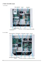
Page 46: ...44 1 Electric Control Box Layout For SCV 750EB For SCV 1400EB...
Page 61: ...59 3 Wiring diagram 3 1 Single unit For SCV 750EB and SCV 1400EB...
Page 62: ...60 For SCV 900EB...
Page 63: ...61 For SCV 1800EB...
Page 78: ...76 5 5 E3 E4 E5 E7 Eb Ed EE EF EP EU Fb Fd Troubleshooting Digital display output...
Page 159: ......
Page 160: ...0 1 234 56 0 7 8 234 0 9 1 7 1 0 6 16 3 5 9 4 260 88 4 260 88 08 88 688 0 4 08 4 6 4A8 60 B...

