


38
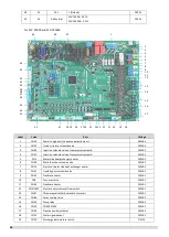
6.4
Compressor and Inverter Module Protection Control
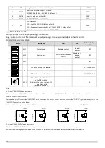
For SCV-750EB and SCV-1400EB:
The protection current for SCV-750EB is 54A, for SCV-750EB is 106A.
Notes:
1.
P4 is the protection for System A, P5 is the protection for System B.
For SCV-900EB and SCV-1800EB:
The protection current for SCV-900EB is 33A, for SCV-1800EB is 60A.
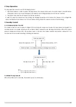
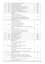
This control protects the compressors from abnormally high currents and protects the inverter modules from abnormally high
temperatures. It is performed for each compressor and inverter module.
Notes:
1. P4 is the protection for System A, P5 is the protection for System B.
When the compressor current rises above protection current, the system displays P4 or P5 protection and all the units stop
running. When the compressor current drops below protection current, the compressor enters re-start control.
Notes:
1. The module temperature is calculated by inverter module.
When the module temperature rises above 100°C, the system displays PL protection and all the units stop running. When the module temperature drops below
70°C, the compressor enters re-start control.
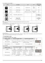
Current > protection current
Current < protection current
Normal operation
Compressor current protection, error code P4/P5 is displayed
Current > protection current
Current < protection current
Normal operation
Compressor current protection, error code P4/P5 is
Module temperature
1
> 100°C
Module temperature
1
< 70°C
Normal operation
Inverter module temperature protection, error code PL is
displayed
When P4 or P5 protection occurs 3
times in 60 minutes, a manual system
restart is required before the system
can resume operation.
CL is displayed when PL error occurs 3
times in 100 minutes, a manual
system restart is required before the
system can resume operation.
CL is displayed when PL error occurs 3
times in 100 minutes, a manual
system restart is required before the
system can resume operation.
Summary of Contents for SCV-1400EB
Page 2: ......
Page 4: ...2...
Page 8: ...6...
Page 26: ...24...
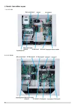
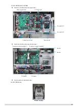
Page 46: ...44 1 Electric Control Box Layout For SCV 750EB For SCV 1400EB...
Page 61: ...59 3 Wiring diagram 3 1 Single unit For SCV 750EB and SCV 1400EB...
Page 62: ...60 For SCV 900EB...
Page 63: ...61 For SCV 1800EB...
Page 78: ...76 5 5 E3 E4 E5 E7 Eb Ed EE EF EP EU Fb Fd Troubleshooting Digital display output...
Page 159: ......
Page 160: ...0 1 234 56 0 7 8 234 0 9 1 7 1 0 6 16 3 5 9 4 260 88 4 260 88 08 88 688 0 4 08 4 6 4A8 60 B...


