


88
5.11
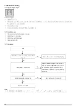
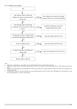
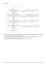
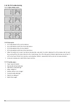
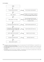
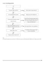
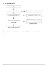
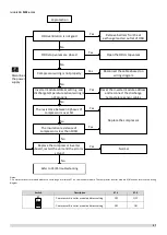
P1 Troubleshooting
Digital display output
Description
For SCV-750EB and SCV-1400EB
P1 indicates suction pipe low pressure protection. When the suction pressure falls below 0.05MPa, the system displays P1
protection and all units stop running. When the pressure rises above 0.15MPa, P1 is removed and normal operation
resumes. When P1 error occurs 3 times in 60 minutes, a manual system restart is required before the system can resume
operation.
P1 another indicates in the standby state or shutdown state, after the compressor stops for 3min, it is determined that the
refrigerant quantity of the refrigerant system of the unit is insufficient through the saturation temperature corresponding to
the high-pressure pressure, the system displays P1 protection, the unit does not start and the protection is not locked;
When the detection pressure returns to above the judgment value, the protection is released and the unit can resume
startup.
P1 the last one indicates during the operation of the compressor of the unit, if the exhaust superheat is too high and lasts
for 30min, report P1 protection first, and then judge the low refrigerant. If the low refrigerant protection is not triggered, P1
protection is removed and the operation is restarted according to the demand.
Error code is displayed on main PCB and user interface.
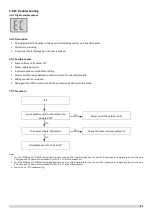
For SCV-900EB and SCV-1800EB
P1 indicates suction pipe low pressure protection. When the suction pressure falls below 0.05MPa, the system displays P1
protection and all units stop running. When the pressure rises above 0.15MPa, P1 is removed and normal operation
resumes. When P1 error occurs 3 times in 60 minutes, a manual system restart is required before the system can resume
operation.
Error code is displayed on main PCB and user interface.
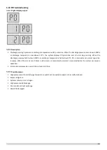
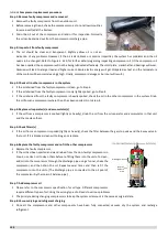
Possible causes
Low pressure switch not connected properly or has malfunctioned.
Insufficient refrigerant.
Low pressure side blockage.
Poor evaporator heat exchange in heating mode.
Insufficient water flow in cooling mode.
Main PCB damaged.
Summary of Contents for SCV-1400EB
Page 2: ......
Page 4: ...2...
Page 8: ...6...
Page 26: ...24...
Page 46: ...44 1 Electric Control Box Layout For SCV 750EB For SCV 1400EB...
Page 61: ...59 3 Wiring diagram 3 1 Single unit For SCV 750EB and SCV 1400EB...
Page 62: ...60 For SCV 900EB...
Page 63: ...61 For SCV 1800EB...
Page 78: ...76 5 5 E3 E4 E5 E7 Eb Ed EE EF EP EU Fb Fd Troubleshooting Digital display output...
Page 159: ......
Page 160: ...0 1 234 56 0 7 8 234 0 9 1 7 1 0 6 16 3 5 9 4 260 88 4 260 88 08 88 688 0 4 08 4 6 4A8 60 B...


