52
2.3
Compressor Inverter Module Board
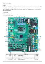
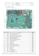
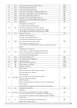
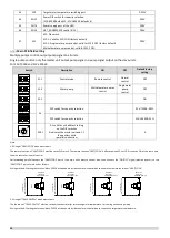
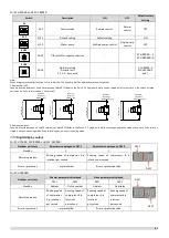
Compressor Inverter Module PCB component
For SCV-750EB and SCV-1400EB
Label
Code
Port
Explanation
Voltage
1
CN1
P-in
Reactor output port
2
CN5
P-out
Reactor input port
3
CN16
L1
Power supply for module board
380-415V
4
CN7
L2
5
CN15
L3
6
CN17
U
Compressor output
7
CN18
V
8
CN19
W
9
CN21
H-SW
High pressure switch
10
S7
module address setting
system A: 00; system B: 01
11
CN27-1
PED board connection port
DC12V/DC5V
12
CN27-2
PED board connection port
DC12V/DC5V
13
CN25
DEBUG
Driver burn port (WizPro200RS programmer)
DC5V
14
CN8
O-Motor
Module Board PTC Relay Control Port/Module Board
Communication Port
DC12V/DC5V
15
CN9
O-Motor
Module Board PTC Relay Control Port/Module Board
Communication Port
DC12V/DC5V
16
CN3
UVW
Fan output port
17
CN26
Fan control power supply output port
DC19V
18
CN39
P N
Fan power supply output port
DC565V
Summary of Contents for SCV-1400EB
Page 2: ......
Page 4: ...2...
Page 8: ...6...
Page 26: ...24...
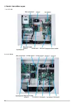
Page 46: ...44 1 Electric Control Box Layout For SCV 750EB For SCV 1400EB...
Page 61: ...59 3 Wiring diagram 3 1 Single unit For SCV 750EB and SCV 1400EB...
Page 62: ...60 For SCV 900EB...
Page 63: ...61 For SCV 1800EB...
Page 78: ...76 5 5 E3 E4 E5 E7 Eb Ed EE EF EP EU Fb Fd Troubleshooting Digital display output...
Page 159: ......
Page 160: ...0 1 234 56 0 7 8 234 0 9 1 7 1 0 6 16 3 5 9 4 260 88 4 260 88 08 88 688 0 4 08 4 6 4A8 60 B...


