


30
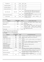
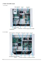
For SCV-750EB and SCV-1400EB:
Component
Wiring diagram label
75kW
140kW
Control functions and states
Water pump
PUMP
●
●
Non-standard component: After the pump is turned on for 2
minutes, detect the water flow switch continuously. The
compressor can be started only after the water flow is
normal.
Inverter compressor 1
BP1
●
●
Control the outlet water temperature. The operating
increased and decreased frequency is 1Hz/s, and is executed
according to the starting platform.
Inverter compressor 2
BP2
●
●
Inverter fan1
FAN1
●
●
Control According to the exhaust pressure of the outdoor
unit, the initial target windshield is operated for the first
60s, and then correct every 20-60s.
Inverter fan 2
FAN2
●
●
Electronic expansion valve
EXV-A
●
●
Step from 0 to 480. Controlled according to discharge
temperature superheat.
Electronic expansion valve
EXV-B
●
●
Step 480P
Electronic expansion valve
EXV-C
●
●
Step from 0 to 480. Controlled according to temperature
difference between economizer plate heat exchanger inlet
and outlet.
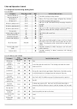
Four-way valve
ST1
●
●
Open
Solenoid valve (defrost)
SV5
●
●
Closed
Solenoid valve (by pass)
SV6
●
●
Open for 600s, then closed.
Solenoid valve (injection)
SV8A/B
●
●
Open
Water flow switch
Water-SW
●
●
After water pump (field supplied) is turned on for 2min, if
water flow switch is open, water pump stops and water flow
error code appears. The compressor can be started after the
water flow is normal.
Water flow switch heater
●
●
Controlled according to ambient temperature, water inlet
temperature and water outlet temperature.
Crank case heater
CCH
●
Controlled according to ambient temperature and discharge
temperature.
For SCV-1800EB:
Component
Wiring diagram
label
180kW
Control functions and states
Inverter compressor
BP1/2
●
Compressor startup program selected according to ambient
temperature
1
.
DC fan motor
FAN
●
Fan run at maximum speed
2
.
Electronic expansion valve
EXV
●
Position (steps) from 0 (fully closed) to 480 (fully open),
controlled according to outdoor ambient temperature,
discharge temperature, suction superheat, compressor speed
and refrigerant system pressure.
Four-way valve
ST1
●
Off
Summary of Contents for SCV-1400EB
Page 2: ......
Page 4: ...2...
Page 8: ...6...
Page 26: ...24...
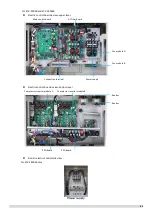
Page 46: ...44 1 Electric Control Box Layout For SCV 750EB For SCV 1400EB...
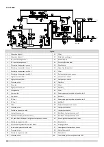
Page 61: ...59 3 Wiring diagram 3 1 Single unit For SCV 750EB and SCV 1400EB...
Page 62: ...60 For SCV 900EB...
Page 63: ...61 For SCV 1800EB...
Page 78: ...76 5 5 E3 E4 E5 E7 Eb Ed EE EF EP EU Fb Fd Troubleshooting Digital display output...
Page 159: ......
Page 160: ...0 1 234 56 0 7 8 234 0 9 1 7 1 0 6 16 3 5 9 4 260 88 4 260 88 08 88 688 0 4 08 4 6 4A8 60 B...


