


90
5.12
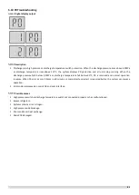
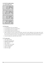
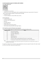
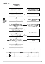
P4, P5 Troubleshooting
Digital display output
Description
1 P4 indicates system A current protection
2 P4 indicates system A DC bus current protection
1 P5 indicates system B current protection
2 P5 indicates system B DC bus current protection
When the compressor current rises above the protection value 33A, the system displays P4 or P5 protection and all units
stop running. When the current returns to the normal range, P4 or P5 is removed and normal operation resumes. When P4
or P5 error occurs 3 times in 60 minutes, a manual system restart is required before the system can resume operation.
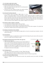
Error code is displayed on main PCB and user interface.
Possible causes
Power supply abnormal.
Poor condenser heat exchange.
High pressure side blockage.
Excess refrigerant.
System contains air or nitrogen.
Inverter module damaged.
Compressor damaged.
Main PCB damaged.
Summary of Contents for SCV-1400EB
Page 2: ......
Page 4: ...2...
Page 8: ...6...
Page 26: ...24...
Page 46: ...44 1 Electric Control Box Layout For SCV 750EB For SCV 1400EB...
Page 61: ...59 3 Wiring diagram 3 1 Single unit For SCV 750EB and SCV 1400EB...
Page 62: ...60 For SCV 900EB...
Page 63: ...61 For SCV 1800EB...
Page 78: ...76 5 5 E3 E4 E5 E7 Eb Ed EE EF EP EU Fb Fd Troubleshooting Digital display output...
Page 159: ......
Page 160: ...0 1 234 56 0 7 8 234 0 9 1 7 1 0 6 16 3 5 9 4 260 88 4 260 88 08 88 688 0 4 08 4 6 4A8 60 B...


