25
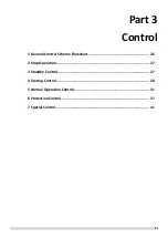
Part 3
Control
1 General Control Scheme Flowchart .......................................................... 26
2 Stop Operation ........................................................................................ 27
3 Standby Control ....................................................................................... 27
4 Startup Control ........................................................................................ 28
5 Normal Operation Control ....................................................................... 31
6 Protection Control ................................................................................... 37
7 Special Control ......................................................................................... 41
Summary of Contents for SCV-1400EB
Page 2: ......
Page 4: ...2...
Page 8: ...6...
Page 26: ...24...
Page 46: ...44 1 Electric Control Box Layout For SCV 750EB For SCV 1400EB...
Page 61: ...59 3 Wiring diagram 3 1 Single unit For SCV 750EB and SCV 1400EB...
Page 62: ...60 For SCV 900EB...
Page 63: ...61 For SCV 1800EB...
Page 78: ...76 5 5 E3 E4 E5 E7 Eb Ed EE EF EP EU Fb Fd Troubleshooting Digital display output...
Page 159: ......
Page 160: ...0 1 234 56 0 7 8 234 0 9 1 7 1 0 6 16 3 5 9 4 260 88 4 260 88 08 88 688 0 4 08 4 6 4A8 60 B...


