155
7.2
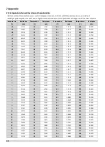
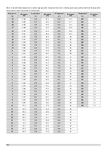
Normal Operating Parameters of Refrigerant System
If the outdoor ambient temperature is high, the system is being run in normal cooling mode with the following settings:
temperature 5°C.
If the outdoor ambient temperature is low, the system is being run in heating mode with the following settings:
temperature 55°C.
The system has been running normally for more than 30 minutes.
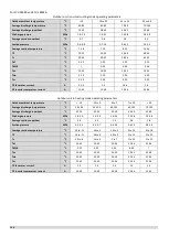
For SCV-750EB and SCV-1400EB
Outdoor unit in normal cooling mode operating parameters
Outdoor ambient temperature
°C
< 10
10 to 25
25 to 35
35 to 48
Average discharge temperature
°C
40-95
65-105
65-105
75-107
Average discharge superheat
°C
15-50
25-60
25-65
30-60
Discharge pressure
MPa
1.6-2.9
2.1-3.0
2.3-3.8
2.6-4.1
Average suction superheat
°C
2-20
2-25
2-25
3-25
Suction pressure
MPa
0.6-1.3
0.7-1.0
0.7-1.3
0.7-1.4
Average suction temperature
°C
1-30
3-30
3-35
5-40
T3
°C
5-40
15-40
30-48
35-54
Tz/7
°C
/
/
/
/
Taf
°C
5-25
5-25
5-25
5-25
T6A/B
°C
/
5-30
8-30
10-40
Twi
°C
10-25
10-25
10-25
10-25
Two
°C
5-20
5-20
5-20
5-20
Tw
°C
5-20
5-20
5-20
5-20
DC fan motor current
A
0.2-4
(
75KW
)
0.2-6
(
140KW
)
1-4
(
75KW
)
1-6
(
140KW
)
1.5-4
(
75KW
)
1.5-6
(
140KW
)
2-4
(
75KW
)
2-6
(
140KW
)
DC inverter compressor current
A
15-45
15-47
20-53
20-53
Outdoor unit in heating mode operating parameters
Outdoor ambient temperature
°C
< -10
-10 to 0
0 to 7
7 to 20
> 20
Average discharge temperature
°C
60-105
60-105
60-105
65-105
65-105
Average discharge superheat
°C
35-55
35-63
30-60
20-55
20-55
Discharge pressure
MPa
1.6-3.5
1.8-3.7
2.0-3.9
2.0-4.0
2.5-4.0
Average suction superheat
°C
-2-10
-5-15
-2-10
0-8
0-10
Suction pressure
MPa
0.2-0.5
0.25-0.65
0.3-0.9
0.6-1.2
0.7-1.4
Average suction temperature
°C
-25 to -5
-22 to 2
-12 to 7
0 to 15
5 to 25
T3
°C
-25 to -11
-22 to 0
-12 to 6
0 to 19
5 to 40
Tz/7
°C
20 to 55
20 to 55
20 to 55
20 to 55
20 to 55
Taf
°C
20-55
20-55
20-55
20-55
20-55
T6A/B
°C
-10-35
0-45
0-40
8-45
/
Twi
°C
20-50
20-50
20-50
20-50
20-50
Two
°C
25-55
25-55
25-55
25-55
25-55
Tw
°C
25-55
25-55
25-55
25-55
25-55
DC fan motor current
A
1-4
(
75KW
)
1-6
(
140KW
)
1-4
(
75KW
)
1-6
(
140KW
)
1-4
(
75KW
)
1-6
(
140KW
)
1-3.5
(
75KW
)
1-5
(
140KW
)
1-3.5
(
75KW
)
1-5
(
140KW
)
DC inverter compressor current
A
10-45
10-45
20-53
20-53
15-45
Summary of Contents for SCV-1400EB
Page 2: ......
Page 4: ...2...
Page 8: ...6...
Page 26: ...24...
Page 46: ...44 1 Electric Control Box Layout For SCV 750EB For SCV 1400EB...
Page 61: ...59 3 Wiring diagram 3 1 Single unit For SCV 750EB and SCV 1400EB...
Page 62: ...60 For SCV 900EB...
Page 63: ...61 For SCV 1800EB...
Page 78: ...76 5 5 E3 E4 E5 E7 Eb Ed EE EF EP EU Fb Fd Troubleshooting Digital display output...
Page 159: ......
Page 160: ...0 1 234 56 0 7 8 234 0 9 1 7 1 0 6 16 3 5 9 4 260 88 4 260 88 08 88 688 0 4 08 4 6 4A8 60 B...


