


70
No
Procedure
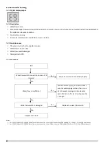
For SCV-750EB and SCV-1400EB
E0/H9
Main PCB or IPM inverter module PCB
dialing code
1
is not correct
Yes
Ensure the dialing code is correct
Notes:
1. Main PCB capability dialing code is designated S4 on the main PCBs (labeled 39 in Part 4, 2.2.1 Main PCB component);
2. Compressor inverter module PCB address dialing code is designated S7 on compressor inverter module PCB.
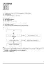
For SCV-900EB and SCV-1800EB
E0/H9
Main PCB or IPM inverter module EEPROM
1
is not connected properly
Yes
Ensure the EEPROM is connected properly
No
EEPROM damaged
Yes
Replace the EEPROM
No
Replace Main PCB or IPM inverter module
PCB
Notes:
1. Main PCB EEPROM is designated IC10 on the main PCBs (labeled 28 in Part 4, 2.2.1 Main PCB component);
2. Compressor inverter module PCB EEPROM is designated IC25 on compressor inverter module PCB (labeled 18 in Part 4, 2.3.1 Compressor Inverter Module PCB
component).
Replace Main PCB or IPM inverter module
PCB
Summary of Contents for SCV-1400EB
Page 2: ......
Page 4: ...2...
Page 8: ...6...
Page 26: ...24...
Page 46: ...44 1 Electric Control Box Layout For SCV 750EB For SCV 1400EB...
Page 61: ...59 3 Wiring diagram 3 1 Single unit For SCV 750EB and SCV 1400EB...
Page 62: ...60 For SCV 900EB...
Page 63: ...61 For SCV 1800EB...
Page 78: ...76 5 5 E3 E4 E5 E7 Eb Ed EE EF EP EU Fb Fd Troubleshooting Digital display output...
Page 159: ......
Page 160: ...0 1 234 56 0 7 8 234 0 9 1 7 1 0 6 16 3 5 9 4 260 88 4 260 88 08 88 688 0 4 08 4 6 4A8 60 B...


