


40
6.9
Water Side Heat Exchanger Temperature Difference Protection Control
Notes:
1.
Twi: Water side heat exchanger inlet temperature;
2.
Two: Water side heat exchanger outlet temperature.
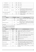
When the temperature difference rises at or above 10°C, the system displays P9 protection and all the units stop running. When
the temperature difference drops below 6°C, the compressor enters re-start control.
6.10
Water Side Heat Exchanger Low Temperature Protection Control
This control protects the water side heat exchanger from ice formation.
Notes:
1. Taf2: Water side heat exchanger anti-freezing temperature 2
6.11
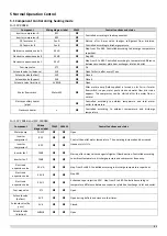
Water Side Heat Exchanger Low Pressure Protection Control
This control protects the water side heat exchanger from ice formation.
Normal cooling mode
In normal cooling mode, when 0.5Mpa≤ Pe < 0.6Mpa for 30s or Pe < 0.5Mpa for 5s, the system displays PC protection and all the
units stop running. When the unit stop, the compressor enters re-start control.
Low leaving water temperature mode
In low water temperature cooling mode, when the suction pressure drops below 0.4Mpa for 30s, the system displays PC
protection and all the units stop running. When the unit stop, the compressor enters re-start control.
∣
Twi-Two
∣
≥ 10°C
∣
Twi-Two
∣
≤ 6°C
Normal operation
Temperature difference protection, error code P9 is displayed
For normal cooling mode:
Taf2 ≤ 3°C for 3s
For low leaving water temperature mode:
Taf2 ≤ -2°C for 3s
For normal cooling mode:
Taf2 > 10°C and unit stops time >3min
For low water outlet cooling mode:
Taf2 > 5°C and unit stops time >7min
Normal operation
Low temperature protection, error code PE is displayed
0.5Mpa≤ Pe < 0.6Mpa for 30s
Or Pe < 0.5Mpa for 5s
Unit stops
Normal operation
Low pressure protection, error code PC is displayed
Pe < 0.4Mpa for 30s
Unit stops
Normal
Low pressure protection, error code PC is
Summary of Contents for SCV-1400EB
Page 2: ......
Page 4: ...2...
Page 8: ...6...
Page 26: ...24...
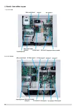
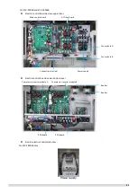
Page 46: ...44 1 Electric Control Box Layout For SCV 750EB For SCV 1400EB...
Page 61: ...59 3 Wiring diagram 3 1 Single unit For SCV 750EB and SCV 1400EB...
Page 62: ...60 For SCV 900EB...
Page 63: ...61 For SCV 1800EB...
Page 78: ...76 5 5 E3 E4 E5 E7 Eb Ed EE EF EP EU Fb Fd Troubleshooting Digital display output...
Page 159: ......
Page 160: ...0 1 234 56 0 7 8 234 0 9 1 7 1 0 6 16 3 5 9 4 260 88 4 260 88 08 88 688 0 4 08 4 6 4A8 60 B...


