


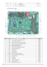


50
43
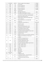
CN7
Target water temperature switching port
DC12V
44
ENC2
Power DIP switch for capacity selection.
(SCV-900EB defaults 2; SCV-1800EB defaults 6 )
DC5V
45
CN74
Power supply port of the HMI
DC9V
46
ENC4
NET_ADDRESS DIP switch (0~15)
DC5V
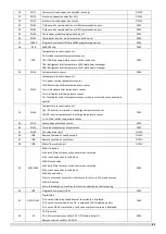
47
S12
S12: Dip switch
S12-1: Valid for S12-1 ON (factory default)
S12-2: Single water pump control, valid for S12-2 OFF (factory default)
Multiple water pumps control, valid for S12-2 ON
。
DC5V
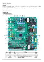
Main PCB field setting
Multiple pumps control: output pump signal on all units.
Single pump control: only the master unit output pump signal, no pump signal output on the slave units.
For
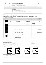
SCV-750EB and SCV-1400EB
Switch
Description
ON
OFF
Default factory
setting
S1-1
Control mode
Remote control
Normal
control
OFF
S1-3
Water pump
Multiple water pumps
control
Single water
pump
control
OFF
S3-1
-
-
-
ON
S4
DIP switch for capacity selection
-
-
SCV-750EB: 0011
DIP switch for capacity selection
SCV-1400EB: 0111
ENC1
0-F valid for unit address setting
on the DIP switches
0 indicates the master unit and 1-F
the auxiliary units
(parallel connection)
-
-
0
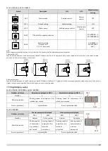
Note:
1. Wiring of “HEAT/COOL” weak electric port
The remote function of “HEAT/COOL” must be set by DIP switch. The remote function “HEAT/COOL” is effective when S1-1or S5-3 is chosen ON, at the same time,
the wire controller is out of control.
Corresponding parallel connect the “HEAT/COOL” port of the main unit’s electric control box, then, connect the “ON/OFF” signal (provide by user) to the
“HEAT/COOL” port of main unit as follows.
Wiring method: Shorting the terminal block CN138 at slave board inside the electric control box to enable the remote function of “HEAT/COOL”.
2.
Wiring of “TEMP-SWITCH” weak electric port
The function of “TEMP-SWITCH” must be set by wired controller for two setting water temperature. For cooling and heating mode.
Wiring method: Shorting the terminal block CN110 at slave board inside the electric control box to choose the target water temperature.
0# electric
control box
“HEAT/COOL” port
C
O
O
L
P
ow
er
(D
C
12
V)
M
ain
co
nt
ro
l b
oa
rd
is
p
ro
vid
ed
0# electric
control box
“HEAT/COOL” port
H
E
A
T
P
ow
er
(D
C
12
V)
M
ain
co
nt
ro
l b
oa
rd
is
p
ro
vid
ed
0# electric
control box
“TEMP-SWITCH” port
P
ow
er
(D
C
12
V)
M
ai
n
co
nt
ro
l b
oa
rd
is
p
ro
vid
ed
0# electric
control box
“TEMP-SWITCH” port
P
ow
er
(D
C
12
V)
M
ai
n
co
nt
ro
l b
oa
rd
is
p
ro
vid
ed
Summary of Contents for SCV-1400EB
Page 2: ......
Page 4: ...2...
Page 8: ...6...
Page 26: ...24...
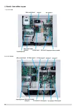
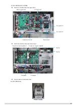
Page 46: ...44 1 Electric Control Box Layout For SCV 750EB For SCV 1400EB...
Page 61: ...59 3 Wiring diagram 3 1 Single unit For SCV 750EB and SCV 1400EB...
Page 62: ...60 For SCV 900EB...
Page 63: ...61 For SCV 1800EB...
Page 78: ...76 5 5 E3 E4 E5 E7 Eb Ed EE EF EP EU Fb Fd Troubleshooting Digital display output...
Page 159: ......
Page 160: ...0 1 234 56 0 7 8 234 0 9 1 7 1 0 6 16 3 5 9 4 260 88 4 260 88 08 88 688 0 4 08 4 6 4A8 60 B...


