


SV800/SV800A User Manual 7 Detailed function description
185
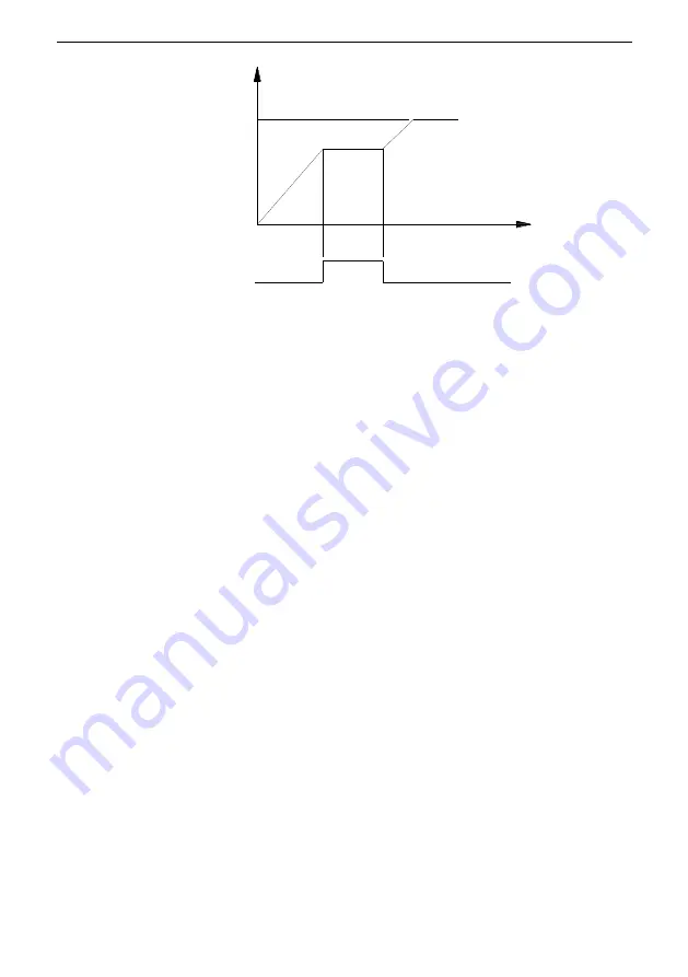
Fig. 7 - 24 Speed keeping by DI
20: Fault reset
21: External fault input (Normal open)
22: External fault input (Normal closed)
The inverter gives “External fault ” when the terminal with function 21 and 22 valid, it locks the
output immediately.
23: Speed increase command UP
24: Speed decrease command DOWN
When UP/DOWN function selected, DI with function 23 and 24 can be used to increase and
decrease the frequency. The related parameters are
E3-05
to
E3-08
.
25: Clear the set of UP/DOWN
26:
Prohibit Drooping function
The DI used to prohibit drooping function. For drooping function, please refer to parameters
d2-18
to
d2-22
.
27: DC braking command
When DC braking command provided by DI, it has some difference with the DC braking mode
during deceleration. When the DI valid, the inverter outputs DC braking current and start the
braking function. Under vector control, the DC braking current set in
d2-09
. For V/F control,
the braking voltage set in
d4-02
. When the DI changes to invalid, after braking time set in
d2-08
,
the inverter blocks the output.
28: Pre-excitation command
Pre-excitation command controlled by multi-function DI. Please select pre-excitation mode in
d2-14
. Only DC pre-excitation mode is supported for SVC control mode. The pre-excitation
command priority is lower than the running, Jog and DC braking command.
29: Reserved
30: Reserved
31: Select Second motor
When second motor selected in b0-00 and the DI with the selected function is valid, the
parameters in b2 group would be selected in the inverter.
Set speed
Time
ON
Speed keeping signal
Output speed
Summary of Contents for SV800 Series
Page 8: ......


