


7 Detailed function description SV800/SV800A User Manual
154
7.3.3 d2: Operating module control parameters
Speed control related function module parameters group.
No.
Name
Set range
Factory default
d2-00
Selection of Motor Driving Mode
0
~
4
0
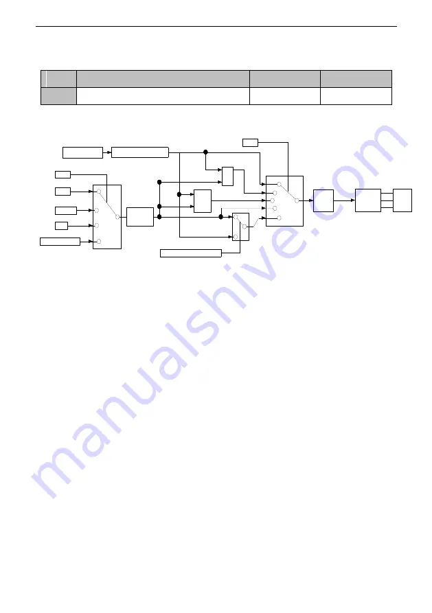
Under vector control, different control mode can be selected, speed control or torque control.
The schematic diagram of the motor drive mode is shown in Fig.7-2:
Fig.7-2 Driving mode selection
0: Speed Control Mode (ASR)
The motor speed is controlled.
1: Torque command negative side priority mode
It will select the smaller value as the actual torque command between the torque output of the
speed loop adjuster the torque input command. Positive and negative symbol considered when
judging.
2:Torque command positive priority mode
It will select the larger value as the actual torque command between the torque output of the
speed loop adjuster the torque input command. Positive and negative symbol considered when
judging.
3: Torque Control Mode (ATR)
The motor torque is controlled.
4: Speed/ torque control switching mode
The control mode can be switched by multi-function terminal (H0-XX = 10). When the terminal
valid, torque control is selected. The switching is smoothly during operation and the motor
speed not changed steeply.
When the priority mode is selected, it can limit the speed range under torque control mode. It
means that even under torque control mode, speed can be controlled by the speed limit.
Speed command
Speed control module
d1-07
d3-01
AI1/2/3
HDI
Communication
MAX
MIN
Speed/Torque switchover
d2-00
Torque
control
module
Inverter
Motor
Torque
command
0
1/2/3
4
5
0
1
2
3
4
Summary of Contents for SV800 Series
Page 8: ......


