Chapter 3: Rackmount and Installation
21
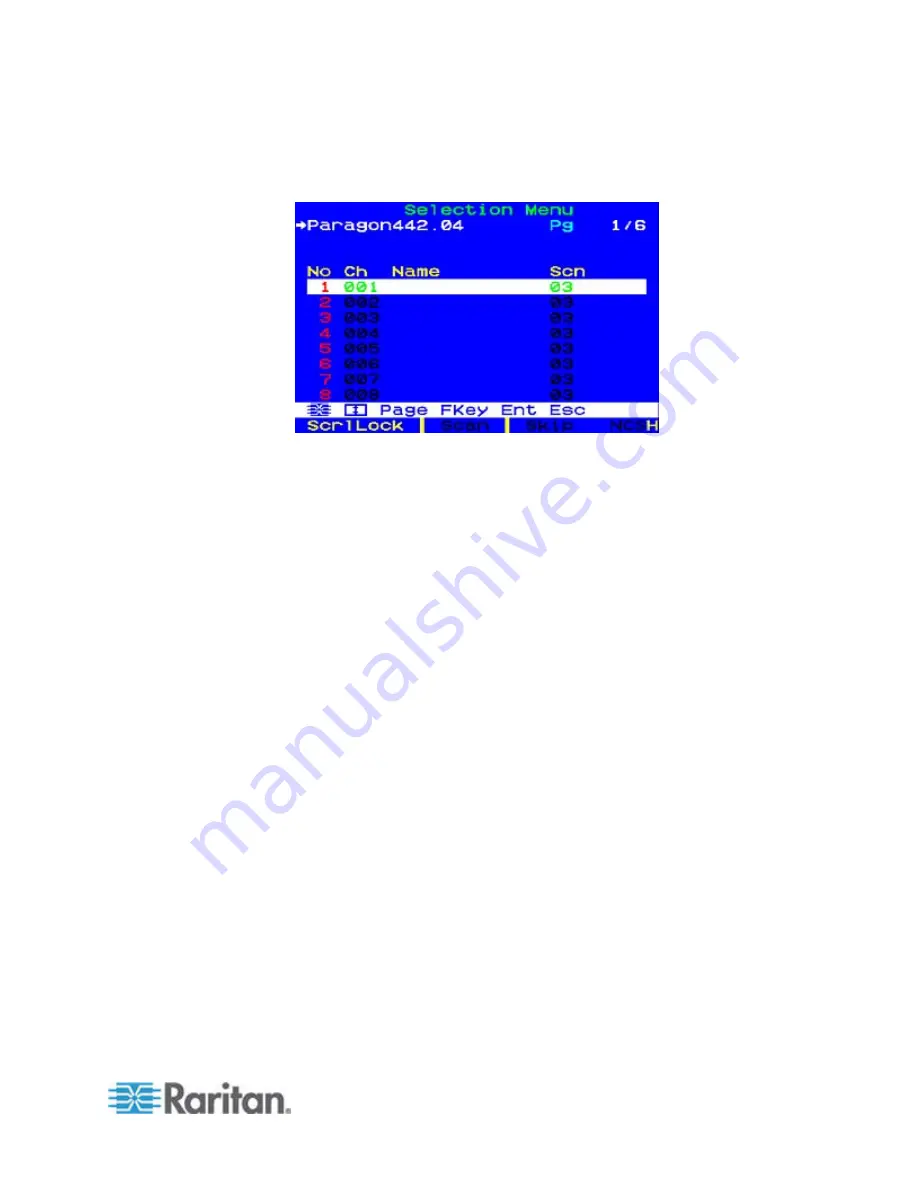
c. The OSUI Selection Menu appears, indicating that the user station
is correctly installed.
4. Repeat steps 2 and 3 for each user station you want to connect to the
Paragon switch.
5. Connect a CIM and the desired server.
a. Connect the cable strands of an appropriate CIM to the
appropriate ports on a server:
P2CIM-APS2 (PS/2 compatible servers) or P2CIM-APS2-B
(IBM BladeCenter Management Module with PS/2 ports):
Plug the HD15 strand into the server’s HD15 VGA video port. Plug
the purple 6-pin mini-DIN keyboard strand into the server’s 6-pin
mini-DIN keyboard port. Plug the light green 6-pin mini-DIN strand
into the server’s 6-pin mini-DIN mouse port.
P2CIM-ASUN (Sun compatible servers):
Plug the HD15 strand into the server’s HD15 VGA video port. Plug
the 8-pin mini-DIN strand into the server’s 8-pin mini-DIN
keyboard/mouse port.
P2CIM-AUSB, P2CIM-AUSB-C (USB compatible servers), or
P2CIM-AUSB-B (IBM BladeCenter Management Module with
USB ports):
Plug the HD15 strand into the server’s HD15 VGA video port. Plug
the USB
Type A
strand into one of the server’s USB
Type A
ports.
P2CIM-APS2DUAL (PS/2 compatible servers):
Connect keyboard, monitor, and mouse cables attached to the
CIM to the appropriate 15-pin female video port and 6-pin mini-DIN
mouse and keyboard ports on the server.
P2CIM-SER,
P2CIM-SER-EU
and AUATC (serial servers,
routers, and so on):
Please see
Connecting Serial Devices to Paragon II System
(on page 195) for installation instructions.
Summary of Contents for PARAGON II Series
Page 22: ......
Page 28: ...Chapter 1 Introduction 6 User Station P2 EUST CIM P2CIM APS2 P2 EUST C Front and Rear Sides ...
Page 257: ......


