3-12
Rev.2.00
Related page
・
P.2-47 “
Wiring to the Connector
,
X4”
・
P.2-48 “
Wiring to the Connector
,
X4”
・
P.3-17 “List of Parameters ”
Damping control
2.14
1st
2.13
Switching
selection
Frequency Filter
2.16
2.18
2.20
2.15
Depth
width
6.41
6.60
6.71
6.72
2.29
2.30
2.28
2.27
2.17
2nd
2.19
2.21
3rd
4th
Smoothing
filter
Gain switching
1.14
2nd setup
1.15
Mode
1.16
Delay time
1.17
Level
1.18
Hysteresis
1.19
Switching
time
6.05
3rd setup
6.06
Scale
factor
2.22
Primary
delay
2.23
Electronic gear
positive conversion
0.09
FIR
Numerator
0.10
Denominator
Motor
External load
RTEX command data
RTEX monitor data
PANATERM/RTEX monitor data
Main
power
supply
Encoder
Velocity
feed forward
1.10
Gain
1.11
Filter
Torque feed
forward
1.12
Gain
1.13
Filter
1.00
Current control
Velocity detection
6.11
Response
setup
Friction compensation
6.07
Additional value
6.08
Positive direction
6.09
Negative direction
Velocity
detection filte
1.03
1st
1.08
2nd
Positional deviation
[Encoder pulse]
Velocity control
command [r/min]
Positional command
speed [r/min]
Torque instruction
TRQ
[0.1 %]
Internal positional
command speed [r/min]
+
-
PP
CP
+
-
+
+
+
+
+
+
+
+
+
+
+
-
Sum of feedback
pulses
[Encoder pulse]
Motor velocity
[r/min]
Electronic gear
reverse conversion
Torque FF
unit conversion
Electronic
gear reverse
conversion
Electronic
gear reverse
conversio
Internal command
position (before filter)
IPOS [Command unit]
Command speed
MSPD
[Command unit/s]
or [r/min]
Target speed
TSPD
[Command unit/s]
or [r/min]
Actual speed ASPD
[Command unit/s]
or [r/min]
Command positional
deviation
PERR
[Command unit]
Command position
(Upstream of filter) CMD_POS
[Instruction unit]
Torque feed forword
TFF
[0.1 %]
Target position
TPOS
[Command unit]
Latch position 1
LPOS1
[Command unit]
Actual position
APOS
[Command unit]
command position
(after filter)
MPOS [Command unit]
Position
instruction
generation
process
●
Profile position control mode (PP)
●
Cyclic position control mode (CP)
Position control
1st
1.05
1.00
2nd
Velocity control
1.01
1st
Proportion Integration
1.06
1.02
1.07
2nd
0.04
Inertia ratio
Torque filter
1.04
1st
1.09
2nd
Two-staged
torque filter
6.42
Time
constant
6.43
Damping
term
Notch filter
2.01
1st
Frequency Width
2.04
2.02
2.05
2nd
2.10
2.11
2.00
Depth
2.03
2.06
2.07
2.08
3rd
2.09
2.12
4th
2.24
2.25
2.26
5th
Adaptive mode
Frequency 1
Load variation suppression
6.23
Compensation
gain
Frequency1
Number of
times
6.24
6.73
6.74
6.75
6.76
Frequency2
Compensation
filter
Estimate
filter
Torque limit
0.13
1st
5.21
Selection
5.22
2nd
*
1
*
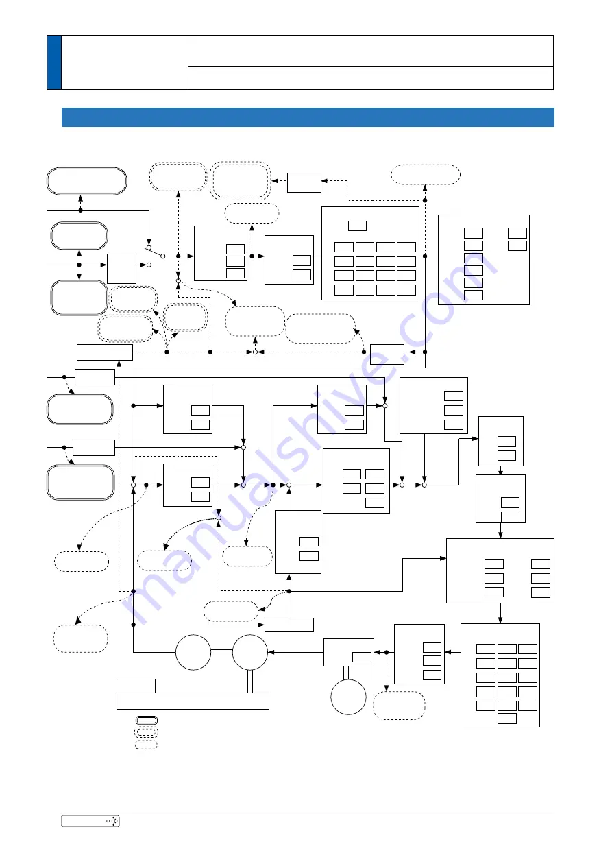
1 The computation reference for the command positional deviation [command unit] can be changed by bit14 for Pr7.23 "
RTEX function extended setup 2".
0.08
Pulse
counts
Velocity feed forward
VFF
[Command unit/s]
or [r/min]
Velocity FF
unit conversion
Velocity offset
value [r/min]
+
-
+
-
*
2
*
2
*
2 The position command on PANATERM can be switched depending on the setting of the bit3 "Command pulse
accumulation value" of Pr7.99 "RTEX function extended setup 6"
.
*
3 When performing trial run function, Z phase search, Frequency characteristic analysis (position loop characteristic)
Sfrom the PANATERM, the driver switches to position control mode internally.
Position Mode
3
2.Outline of Con
trol Mode
Setup
Block Diagram of Control Mode
Summary of Contents for MINAS A6N Series
Page 14: ...14 Rev 2 00 MEMO ...
Page 30: ...1 16 Rev 2 00 MEMO ...
Page 104: ...2 74 Rev 2 00 MEMO ...
Page 228: ...3 124 Rev 2 00 MEMO ...
Page 491: ...7 108 Rev 2 00 MEMO ...


