Ottobock | 15
3R106, 3R106=KD, 3R106=ST, 3R106=HD
Attention!
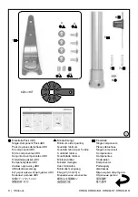
It is not allowed to loosen, shift, or replace the connection adapter!
For the prosthetic fitting of hip disarticulations, it is of utmost importance that the specially
adapted knee joint version 3R106=HD is used.
3 Technical data
Order number
3R106
3R106=KD
3R106=ST
3R106=HD
Proximal connection
Pyramid
adapter
Lamination
anchor
Thread
(M26x1.5)
Pyramid
adapter
Distal connection
Tube clamp ⌀ 30 mm
Knee flexion angle
170°
Weight
760 g
755 g
765 g
790 g
System height
162 mm
184 mm
180 mm
164 mm
Proximal system height up
to alignment reference point
-6 mm
16 mm
12 mm
-4 mm
Distal system height up to
alignment reference point
168 mm
Max. user weight
100 kg / 220 lbs
Mobility Grade
2 + 3
4 Handling
Use 2Z11=KIT
INFORMATION
: The connection area of the prosthetic knee joint can be protected against
scratches with the protective film of the 2Z11=KIT during alignment in the workshop and testing
in the trial fitting area.
•
Use the protective film as illustrated in the accompanying document for the 2Z11=KIT.
•
Remove the protective film before the patient leaves the fitting area.
4.1 Alignment
The three-dimensional arrangement of the prosthetic socket and the modular components affects
the static and dynamic functions of the prosthesis.
The advantages of the 3R160 Knee Joint can only be made optimal use of in case of a correct alignment.
The optimal residual limb position must be anticipated when positioning the socket connec-
tor.
Plumb lines in the frontal and sagittal planes (drawn from the hip joint’s center of rotation and
marked during plaster cast taking and trial fitting of the test socket) will facilitate correct position
-
ing of the lamination anchor or socket adapter.
To align the prosthesis please proceed in two steps:
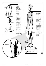
1. First make the bench alignment using an alignment tool (such as 743L200 L.A.S.A.R. Assembly
or PRO.S.A. Assembly 743A200).
2. Then use 743L100 L.A.S.A.R. Posture for static alignment optimization.
4.1.1 Bench alignment with alignment tool
(the following steps refer to Fig. 7)
Position the middle of the foot
30 mm anterior
to the alignment reference line.
Add 5 mm to the required heel height of the foot. Set correct outward rotation of the foot.
Summary of Contents for 3R106
Page 3: ...Ottobock 3 3R106 3R106 KD 3R106 ST 3R106 HD 3 4 2 1 3 4 2 5 7 7a 6...
Page 133: ...Ottobock 133 3R106 3R106 KD 3R106 ST 3R106 HD 4 3 2 1 3R106 KD 3R106 ST 4 3 2 2 4 E 4 F F 4...
Page 152: ...152 Ottobock 3R106 3R106 KD 3R106 ST 3R106 HD 4 6 300 3 5 5 6 6 1 6 2 EU 2017 745 CE...
Page 159: ...Ottobock 159 3R106 3R106 KD 3R106 ST 3R106 HD 519L5 4 6 300 5 6 6 1 6 2 CE 2017 745 CE...
Page 160: ...160 Ottobock 3R106 3R106 KD 3R106 ST 3R106 HD...
Page 161: ...Ottobock 161 3R106 3R106 KD 3R106 ST 3R106 HD...


