16 | Ottobock
3R106, 3R106=KD, 3R106=ST, 3R106=HD
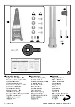
Clamp the knee joint using the appropriate adapter inserts. For bench alignment,
the align-
ment reference line should run through the upper anterior axis
(alignment reference point).
At that point the pyramid base should be horizontal. Pay attention to the knee ground distance
and outward rotation of the knee (adapter inserts provide for a rotation of approx. 5°). Recom-
mended positioning of the alignment reference point: 20 mm above the medial tibial plateau.
Connect the foot to the modular knee joint using the enclosed tube adapter.
Attention!
1.
Do not clamp the tube into a vise!
Cut the tube using 719R2 Tube Cutter placed
at a right angle to the tube.
2. Afterwards carefully debur the inside and outside of the tube using the 718R1
Interior and Exterior Pipe Reamer.
3. It is
indispensable
to insert the tube until it is fully seated inside the integrated
tube clamp.
4. Tighten the cap screw using the 710D1 Torque Wrench:
Torque: 10 Nm
.
5.
For trial fitting:
Tighten the adjacent 506G3 Set Screws of the tube adapter to
a torque of
10 Nm
using the 710D4 Torque Wrench. To finish the prosthesis:
Apply 636K13 Loctite to the set screws, pre-tighten the adjacent set screws to
a torque of
10 Nm
, and then tighten all four set screws to a torque of
15 Nm
.
For reasons of structural strength, the residual pieces of cut tube adapters must not
be used as components in prostheses.
Mark the center of the socket proximally and distally on the lateral side. Draw a line through
both marks from socket brim to the distal end of the socket.
Now position the socket such that the alignment reference line passes through the proximal
center mark of the socket. Set the socket flexion to somewhere between 3° and 5°; however,
the individual situation (e.g. hip joint contractures) must be taken into account and, if necessary,
more flexion should be provided. Also pay attention to the ischial tuberosity to ground distance.
Attention!
If the residual limb flexion is not taken into account, the joint will be positioned too
far to the front. This will lead to malfunction and premature wear. If required, use the
4R118 Adapter Plate for optimal positioning of the prosthetic knee joint.
Connect the socket and modular knee joint using a corresponding adapter (e.g. 4R111, 4R41,
4R55, 4R51 Socket Adapter).
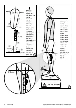
4.1.2 Static alignment optimization using 743L100 L.A.S.A.R. Posture
(the following steps refer to Fig. 8)
The bench alignment can be substantially improved using L.A.S.A.R. Posture. In order to ensure
appropriate stability combined with easy swing phase initiation, please proceed as follows:
To make the load line visible, the transfemoral amputee stands on the L.A.S.A.R. Posture with
the prosthetic side on the force plate and with the other leg on the height compensation panel.
The prosthesis side should be sufficiently loaded (> 35 % of the body weight).
Now adapt the alignment by only
adjusting the plantar flexion of the foot.
The
load line (laser
line) should be approx.
35 mm (1.38 in ) anterior to the upper front knee axis
(see Fig. 8).
After step 2, dynamic optimization can take place between parallel bars.
Summary of Contents for 3R106
Page 3: ...Ottobock 3 3R106 3R106 KD 3R106 ST 3R106 HD 3 4 2 1 3 4 2 5 7 7a 6...
Page 133: ...Ottobock 133 3R106 3R106 KD 3R106 ST 3R106 HD 4 3 2 1 3R106 KD 3R106 ST 4 3 2 2 4 E 4 F F 4...
Page 152: ...152 Ottobock 3R106 3R106 KD 3R106 ST 3R106 HD 4 6 300 3 5 5 6 6 1 6 2 EU 2017 745 CE...
Page 159: ...Ottobock 159 3R106 3R106 KD 3R106 ST 3R106 HD 519L5 4 6 300 5 6 6 1 6 2 CE 2017 745 CE...
Page 160: ...160 Ottobock 3R106 3R106 KD 3R106 ST 3R106 HD...
Page 161: ...Ottobock 161 3R106 3R106 KD 3R106 ST 3R106 HD...

