3.4 Main Circuit Wiring
38
3.4.4 Wiring the Encoder Connector (CN2)
• Separate the encoder cable at least 300 mm from power lines (i.e., high-voltage lines
such as the power supply line and servomotor main circuit cable).
• Do not bundle or run the encode cable in the same duct with power lines.
• Be sure that the maximum wiring length of the encoder cable is 20 m.
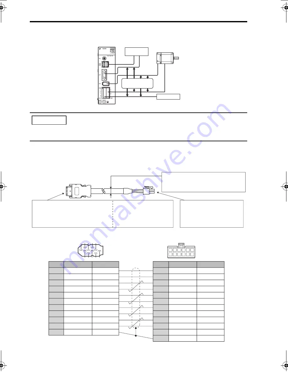
Connection Diagram for Standard Encoder Cable
The connection diagram for the standard cable (JZSP-CHP800-
cable with connectors on both
ends) is shown below. If the encoder cable is prepared by the customer, refer to the diagram below
and wire the cable correctly.
Note: Confirm pin numbers on the connector as well.
Power Supply
Controller
Separate by
300 mm or more
IMPORTANT
SERVOPACK End Connector
T(Viewed from soldered side)
Servomotor End Connector
(Viewed from cable insertion side)
Shield wire
6
5
4
3
2
1
12 11 10
8
7
9
9
7 5 3 1
2
4
6
8
10
SERVOPACK end
Applicable wires
For encoder power supply: AWG22 (0.33 mm
2
)
For other signal wires: AWG26 (0.12 mm
2
)
Cable Finished Diameter:
φ
9
mm max.
Motor end
Receptacle: 5557-12R-210
Terminals: 5556T2 (Chain) or
5556T2L(Loose wires)
(Molex)
Crimp type (Gray)
Plug and Cable Cover Set: 545
99
-1005
Plug Housing: 5120
9
-1001
Crimp Terminals: 5
9
351-8087(Chain) or
5
9
351-8187 (Loose wires)
(Molex)
Soldered type (Black)
Shell Kit: 36310-3200-008
Receptacle: 36210-0100FD (3M)
Pin No.
Signal Name
1
2
3
4
5
6
7
8
9
10
Shell
PG5V
PG0V(GND)
Phase A (+)
Phase A (-)
Phase B (+)
Phase B (-)
Phase /Z
Phase U
Phase V
Phase W
—
Lead Color
Red
Black
Blue
Blue/White
Yellow
Yellow/White
Purple
Gray
Green
Orange
Shield
Red
Black
Blue
Blue/White
Yellow
Yellow/White
Purple
Gray
Green
Orange
—
Shield
Lead Color
Pin No.
Signal Name
1
2
3
4
5
6
7
8
9
10
11
12
PG5V
PG0V(GND)
Phase A (+)
Phase A (-)
Phase B (+)
Phase B (-)
Phase /Z
Phase U
Phase V
Phase W
—
FG
TOEP_C710806_03A_1_0.book Seite 38 Montag, 2. Juli 2007 3:55 15


