Installation Orientation and Space
1
-
11
Installation Orientation and Space
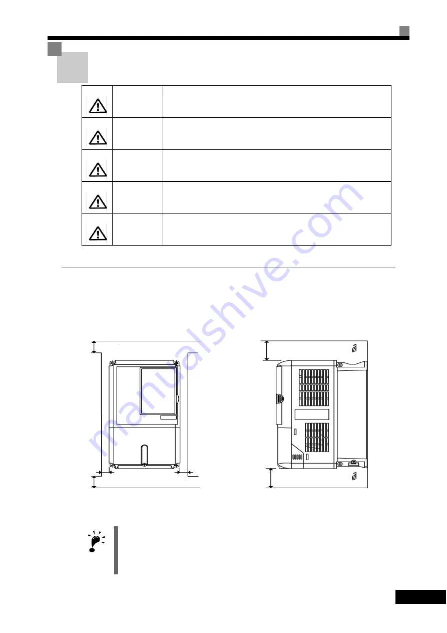
Inverter Installation Orientation and Space
Install the Inverter vertically so as not to reduce the cooling effect. When installing the Inverter, always
provide the following installation space to allow normal heat dissipation.
Fig 1.9 Inverter Installation Orientation and Space
WARNING
Provide an appropriate stopping device on the machine side to secure safety. (
A holding brake is not a stopping device for securing safety) Not doing so may
result in injury.
WARNING
Provide an external emergency stopping device that allows an instantaneous
stop of operation and power interruption. Not doing so may result in injury.
Caution
Be sure to install the product in the correct direction and provide specified
clearances between the Inverter and control panel or with other devices to
allow for proper cooling. Not doing so may result in fire or malfunction.
Caution
Do not allow foreign objects to enter inside the product. Doing so may result in
fire and malfunction.
Caution
Do not apply any strong imact. Doing so may result in damage to the product
or malfunction.
IMPORTANT
1. The same space is required horizontally and vertically for both Open Chassis (IP00) and Enclosed Wall-
mounted (IP20, NEMA 1) Inverters.
2. Always remove the protection covers before installing a 200 or 400 V Class Inverter with an output of
18.5 kW or less in a panel.
Always provide enough space for suspension eye bolts and the main circuit lines when installing a 200 or
400 V Class Inverter with an output of 22 kW or more in a panel.
50 mm min.
50 mm min.
30 mm min.
120 mm min.
120 mm min.
Air
Air
Vertical Space
Horizontal Space
30 mm min.


